
Relay 3 Click


- Order number: MIKROE-3357
- Manufacturer product ID: MIKROE-3357
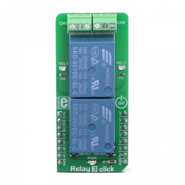
Besides two relays, the Click board™ contains all the necessary electronic components for driving the relay coils. Two LED indicators provide visual feedback about the activity of the relays. Although it can withstand up to 7A through its contacts, the life expectancy of the relay drops proportionally with the current through the contacts. Therefore, Relay 3 click is a good solution for power or signal switching in a range of low to medium power applications, including domestic appliances, office machines, audio equipment, etc.
How does it work?
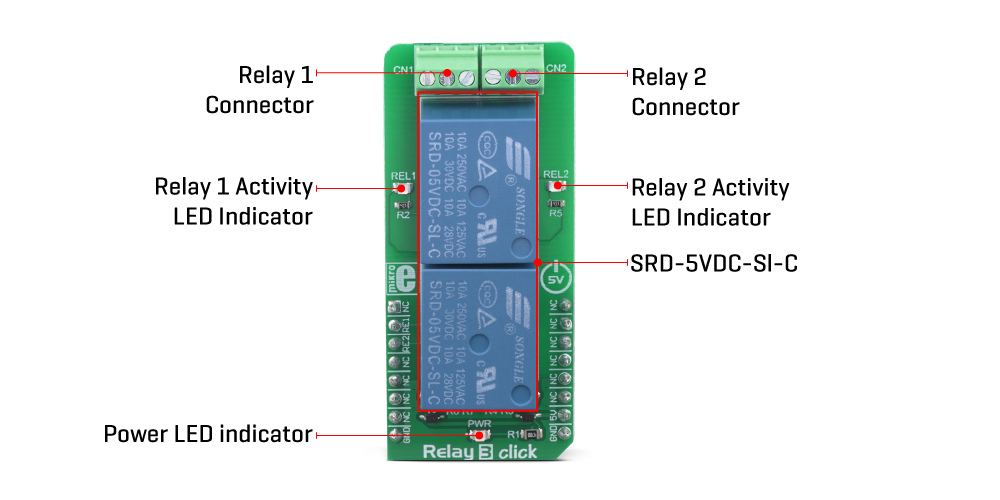
Relay click features two SRD-05VDC-SL-C small-size relays, from SongleRelays. These are reliable relays in a sealed plastic housing, offering good isolation. Despite its size, the SRD-05VDC-SL-C relay is able to withstand up to 7A and 220V AC/28V DC. It can endure up to 105 operations while loaded, and even up to 107 with no load applied. This relay is of a single-pole-double-throw type: when the coil is energized, it will attract the internal switching elements and close one of the contacts, while opening the other contact at the same time. Normally Closed contacts are usually labeled with NC, while Normally Open contacts are labeled as NO.
These relays are designed so that their coils can be easily activated by relatively low currents and voltages. The SRD-05VDC-SL-C relay can be operated with 5V, making it a good choice for activating it by an MCU pin. However, to provide sufficient current for the activation, an additional MOSFET has to be used. Gates of two MOSFETS (one for each relay) are controlled by the MCU pins, therefore are routed to the mikroBUS™. The gates are routed to RST and CS pins of the mikroBUS™ and are labeled as RE1 and RE2, respectively.
There are two LEDs (yellow) which are used to indicate the activity state of the relay. When the current flows through the MOSFET, the coil will be energized, and the relay will be activated. This current also flows through these LEDs, indicating that the relay is active. The LEDs are labeled according to the relay they are connected to: REL1 for the Relay 1, and REL2 for the Relay 2.
A Schottky diode is connected across the relay coil, preventing the back-EMF which can be generated because of the inert nature of the coil. The back EMF can have an adverse effect on the circuit and can potentially damage the control circuit. The diode is connected in the inverse direction, allowing the back-EMF to discharge through the relay coil, instead.
Each relay is equipped with the 3-pole screw terminal, rated for up to 6A. Therefore, the maximum current through the connected load should not exceed this value. However, as already mentioned above, high current negatively affects the life expectance of the relay itself, so switching large currents should be avoided. The middle pole of the screw terminal is connected to the common terminal of the relay (COM) while two other poles are the NC and NO contacts of the relay. Having both NC and NO contacts is useful, expanding the implementation possibilities of Relay 3 click.

DO NOT TOUCH THE BOARD WHILE THE EXTERNAL POWER SUPPLY IS ON!
Note: Relay 3 click has exposed pins/pads. To stay safe take precaution when applying high voltage to the click. The click is to be used by trained personnel only when applying high voltage.
Specifications
| Type | Relay |
| Applications | Relay 3 click is a good solution for power or signal switching in a range of low to medium power applications, including domestic appliances, office machines, audio equipment, etc. |
| On-board modules | SRD-05VDC-SL-C, small-size sealed relays from Songle Relay |
| Key Features | Two small-sized SPDT relays in a sealed plastic housing. LED indicators for indicating the activity of each relay. Screw terminals allow secure connection of the load. Protection from back-EMF generated as a result of the coil inductance. |
| Interface | GPIO |
| Input Voltage | 5V |
| Click board size | L (57.15 x 25.4 mm) |
Pinout diagram
This table shows how the pinout on Relay 3 Click corresponds to the pinout on the mikroBUS™ socket (the latter shown in the two middle columns).
| Notes | Pin | Pin | Notes | ||||
|---|---|---|---|---|---|---|---|
| NC | 1 | AN | PWM | 16 | NC | ||
| RE1 | RST | 2 | RST | INT | 15 | NC | |
| RE2 | CS | 3 | CS | RX | 14 | NC | |
| NC | 4 | SCK | TX | 13 | NC | ||
| NC | 5 | MISO | SCL | 12 | NC | ||
| NC | 6 | MOSI | SDA | 11 | NC | ||
| NC | 7 | 3.3V | 5V | 10 | +5V | Power Supply | |
| Ground | GND | 8 | GND | GND | 9 | GND | Ground |
Relay 3 click maximum ratings
| Description | Min | Typ | Max | Unit |
|---|---|---|---|---|
| Operational Current Range (28V DC / 220V AC) | 0 | - | 6 | A |
| Operational Voltage Range (AC) | 0 | - | 220 | V |
| Operational Voltage Range (DC) | 0 | - | 28 | V |
| Mechanical Endurance | 0 | - | 100,000 | operations |
Onboard settings and indicators
| Label | Name | Default | Description |
|---|---|---|---|
| LD1 | PWR | - | Power indicator LED |
| LD2 | REL1 | - | Relay 1 activity LED indicator |
| LD3 | REL2 | - | Relay 2 activity LED indicator |
Software support
We provide a library for the Relay 3 Click on our LibStock page, as well as a demo application (example), developed using MikroElektronika compilers. The demo can run on all the main MikroElektronika development boards.
Library Description
The library contains functions for turning on/off relays 1 and 2. Library contains functions for turning on/off relays 1 and 2 after a defined period of time.
Key functions:
void relay3_relayOn( uint8_t relay_ )- Turns selected relay on.void relay3_relayOff( uint8_t relay_ )- Turns selected relay off.void relay3_onDelay( uint8_t relay_, uint8_t units_, uint16_t time_ )- Turns selected relay on after a defined period of time in selected units of time.void relay3_offDelay( uint8_t relay_, uint8_t units_, uint16_t time_ )- Turns selected relay off after a defined period of time in selected units of time.
Examples description
The application is composed of three sections :
- System Initialization - Initializes LOG functionality, initializes RST and CS pins as OUTPUTs.
- Application Initialization - Initializes GPIO driver.
- Application Task - Activates relays 1 and/or 2 based on user input.
void applicationTask( )
{
dataReady = UART_Rdy_Ptr( );
if (dataReady != 0)
{
receivedData = UART_Rd_Ptr( );
switch (receivedData)
{
case '1' :
{
relay3_case1( );
break;
}
case '2' :
{
relay3_case2( );
break;
}
case '3' :
{
relay3_case3( );
break;
}
default :
{
mikrobus_logWrite( "wrong command", _LOG_LINE );
break;
}
}
}
}
Additional Functions
void relay3_case1()- Turns relay 1 on/offvoid relay3_case2()- Turns relay 2 on/offvoid relay3_case3()- Turns relay 3 on/off
The full application code, and ready to use projects can be found on our LibStock page.
Other mikroE Libraries used in the example:
UART
Additional notes and informations
Depending on the development board you are using, you may need USB UART click, USB UART 2 click or RS232 click to connect to your PC, for development systems with no UART to USB interface available on the board. The terminal available in all MikroElektronika compilers, or any other terminal application of your choice, can be used to read the message.