
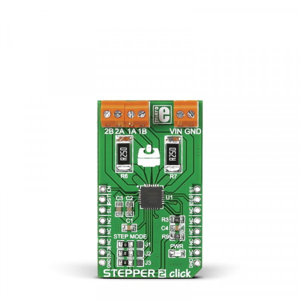
Stepper 2 click


- Order number: MIKROE-1926
- Manufacturer product ID: MIKROE-1926
Stepper 2 click is a complete solution for driving bipolar stepper motors with full/half and micro-steps. It features the A4988 IC from Allegro Microsystems with DMOS low RDSON drivers on its outputs, which ensure high efficiency and reliable operation of the internal H-Bridges. This IC has the integrated translator section, used to simplify the control: using simple step control inputs from the host MCU, the stepper motor can be driven in both directions, with the predetermined step sizes. In addition, the output current is regulated allowing for noiseless operation of the stepper motor, with no resonance and ringing typically observed at unregulated stepper driver designs.
Additional features of the Stepper click include under-voltage, shoot-through, short circuit, overcurrent and thermal protection, so the Click board™ can operate reliably. With its input voltage range up to 35V, it can drive a wide range of stepper motors with up to 2A max. Due to simplicity of the step motor control, as well as the selection of various stepping modes offered by this Click board™, it is a perfect solution for building various applications that require precise and reliable stepper motor control, such as the movement control of beds, heads, and assemblies of various CNC plotting, milling and 3D printer designs.
HOW DOES IT WORK?
Stepper click uses the A4988, a micro-stepping driver IC with a translator and overcurrent protection, from Allegro Microsystems. This is a highly integrated IC, which offers a very simple bipolar stepper motor control interface, thanks to the integrated translator section. This section controls the output drivers, providing smooth action of the stepper motor. By controlling the current intensity and its decay throughout the rotation cycle, a constant torque is achieved for every position. The current regulator uses an internal comparator, DA converter (DAC), and external sensing resistor. The current is limited by the sensing resistor to about 1.6A (for a reference voltage of 3.3V). Absolute current limit on this IC is 2.1A, after which the overcurrent protection is activated.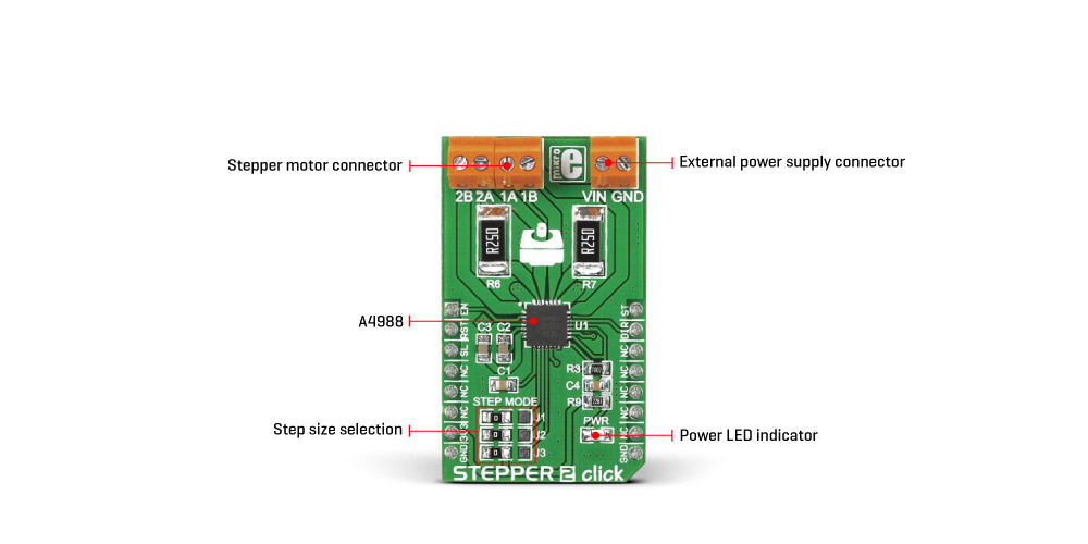
A LOW to HIGH transition on the STEP pin of the A4988 IC will perform one rotational step. The direction of the rotation is controlled by the logic state on the DIR pin (routed to the mikroBUS™ INT pin, labeled as DIR). The step size is determined by three pins: MS1, M2, and MS3. It is possible to work with five-movement step sizes, ranging from full step size up to sixteenth step size. MS1, MS2, and MS3 pins are routed to the SMD jumpers labeled as STEP MODE (J1, J2, and J3), allowing step size to be selected by moving each of them according to the truth table below.
This device supports the Sleep mode, which is activated by a LOW logic level on the SLEEP pin. This will power down the unused sections of the A4988 IC, reducing power consumption to a minimum. After the wake-up event (logic HIGH on the SLEEP pin), at least 1ms of delay is required until the charge pump capacitors are recharged, allowing normal operation of the output stage drivers.
The #ENABLE pin allows the host MCU to enable or disable the output stage MOSFETs of the A4988 IC. Asserting this pin to a LOW logic level enables the output stage. The #RESET pin is used to set DACs and the phase current polarity to the initial Home state. The #ENABLE pin is routed to the AN (labeled as EN), while the #RESET pin is routed to the RST pin of the mikroBUS™, allowing the host MCU to control the IC via these pins.
The Click board™ is equipped with the input and output screw terminals. The terminal labeled as CN1 on the schematic is used to connect the external power supply, which should stay in the range from 8V to 35V. The stepper motor can be connected via the CN2 and CN3 screw terminals, with their input terminals labeled as 1A, 1B, and 2A, 2B. The logic section and the reference voltage pin of the IC are powered via the 3.3V mikroBUS™ rail.
MICROSTEP RESOLUTION CONFIGURATION
| Step size: | Full | Half | 1/4 | 1/8 | 1/16 |
|---|---|---|---|---|---|
| MS1 | L | H | L | H | H |
| MS2 | L | L | H | H | H |
| MS3 | L | L | L | L | H |
SPECIFICATIONS
| Type | Stepper |
| Applications | This Click board™ is a perfect solution for building various applications that require a precise and reliable stepper motor control, such as the movement control of beds, heads, and assemblies of various CNC plotting, milling, and 3D printer designs. |
| On-board modules | A4988, a micro-stepping driver IC with a translator, from Allegro Microsystems, LLC. |
| Key Features | Integrated translation section used to simplify the control, ability to run in full, half, quarter, eighth and sixteenth step, undervoltage, overcurrent and thermal protection, etc. |
| Interface | GPIO |
| Compatibility | mikroBUS |
| Click board size | M (42.9 x 25.4 mm) |
| Input Voltage | 3.3V |
PINOUT DIAGRAM
This table shows how the pinout on Stepper 2 click corresponds to the pinout on the mikroBUS™ socket (the latter shown in the two middle columns).
| Notes | Pin | Pin | Notes | ||||
|---|---|---|---|---|---|---|---|
| Chip Enable | EN | 1 | AN | PWM | 16 | ST | Step trigger |
| Reset | RST | 2 | RST | INT | 15 | DIR | Direction |
| Sleep | SL | 3 | CS | RX | 14 | NC | |
| NC | 4 | SCK | TX | 13 | NC | ||
| NC | 5 | MISO | SCL | 12 | NC | ||
| NC | 6 | MOSI | SDA | 11 | NC | ||
| Power supply | +3.3V | 7 | 3.3V | 5V | 10 | NC | |
| Ground | GND | 8 | GND | GND | 9 | GND | Ground |
STEPPER 2 CLICK ELECTRICAL SPECIFICATIONS
| Description | Min | Typ | Max | Unit |
|---|---|---|---|---|
| External power supply voltage | 8 | - | 35 | V |
| Current limit | - | - | 1.6 | A |
| Step size | 1 | - | 1/16 | step |
ONBOARD SETTINGS AND INDICATORS
| Label | Name | Default | Description |
|---|---|---|---|
| PWR | PWR | - | Power LED indicator |
| J1-J3 | STEP MODE | Left | Step size selection: left position L, right position H (settings in the truth table) |
| CN1 | VIN | - | External power supply connector |
| CN2 | 2A,2B | - | Stepper motor coil 2 connector |
| CN3 | 1A,1B | - | Stepper motor coil 1 connector |
SOFTWARE SUPPORT
We provide a library for Stepper 2 click on our Libstock page, as well as a demo application (example), developed using MikroElektronika compilers and mikroSDK. The provided click library is mikroSDK standard compliant. The demo application can run on all the main MikroElektronika development boards.
Library Description
The library carries everything needed for stepper motor control including speed
and acceleration setup. The library is also adjustable to working on different amounts of ticks per second, also speed and acceleration can be provided in float format. The buffer used for movement calculation is defined by the user so this library can be adjusted for MCUs with very limited RAM resources. Check the documentation for more details on how to use it.
Key functions:
uint8_t stepper2_setSpeed( float minSpeed, float maxSpeed, float accelRatio, T_STEPPER2_OBJ obj )- Function for setting the motor speed.uint8_t stepper2_setRoute( const uint8_t direction, uint32_t steps, T_STEPPER2_OBJ obj )- Setup new route.void stepper2_start( T_STEPPER2_OBJ obj )- Start motor movement.
Examples Description
The application is composed of three sections:
- System Initialization - Initializes all GPIO pins found on Stepper_2 Click and timer to 1ms interrupt.
- Application Initialization - The first segment initializes the driver and stepper control. The second segment setup limits movement, maximum and minimum speed, and acceleration ratio. The third segment enables the motor and sets up a new route which will be called from the application task.
- Application Task - (code snippet) - Sequentially moves the motor. The first part of the sequence executes movement until the end. The second part stops the motor movement after one second and continues the sequence after two seconds.
void applicationTask()
{
stepper2_start( (T_STEPPER2_OBJ_P)&myStepper );
while( myStepper.status.running )
stepper2_process( (T_STEPPER2_OBJ_P)&myStepper );
Delay_ms( 2000 );
stepper2_start( (T_STEPPER2_OBJ_P)&myStepper );
Delay_ms( 1000 );
stepper2_stop( (T_STEPPER2_OBJ_P)&myStepper );
Delay_ms( 2000 );
}
In addition to the library function calls example carries the necessary Timer ISR and Timer initialization. Check the Timer initialization settings and update it according to your MCU - Timer Calculator.
The full application code, and ready to use projects can be found on our Libstock page.
Additional notes and information
Depending on the development board you are using, you may need USB UART click, USB UART 2 click or RS232 click to connect to your PC, for development systems with no UART to USB interface available on the board. The terminal available in all MikroElektronika compilers, or any other terminal application of your choice, can be used to read the message.
MIKROSDK
This click board is supported by mikroSDK - MikroElektronika Software Development Kit. To ensure proper operation of mikroSDK compliant click board demo applications, mikroSDK should be downloaded from the LibStock and installed for the compiler you are using.
- Do you have any questions concerning this product?
- mikroBUS™ Standard specification
- LibStock: mikroSDK
- Learn article: Stepper motors
- Stepper 2 click example on Libstock
- Stepper 2 click schematic
- A4988 datasheet
- Stepper 2 click: 2D and 3D files
- Click Boards™ Catalog
- Further products by MikroElektronika