
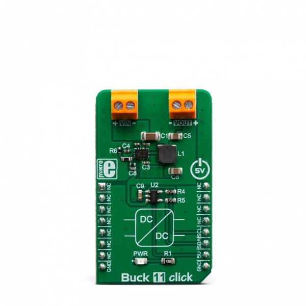
Buck 11 click


- Order number: MIKROE-3438
- Manufacturer product ID: MIKROE-3438
The LMR36015 has a wide voltage input range, which is one of its key features. It can sustain transients up to 66V at its input, making it compliant with the surge immunity requirements of IEC 61000-4-5. It also features a set of standard protection options, found on many similar devices: undervoltage lockout, short circuit protection, thermal shutdown, etc. The Click board™ can be used for a wide range of applications that require 3.3V, including field embedded applications, sensors, PLC modules, video surveillance systems, and similar applications that require step-down conversion to 3.3V.
How does it work?
Buck 11 click is equipped with the LMR36015, a synchronous step-down converter, from Texas Instruments. This is an advanced integrated step-down converter, which requires a minimum number of external components, readily available on the market. It utilizes a peak-current-mode control architecture, which along with the automatic PFM/PWM mode switching, ensures a very good efficiency. The LMR36015 buck converter features over-current, under-voltage, and thermal protection, making Buck 11 click a robust and reliable power supply solution.
The output voltage is determined by the feedback voltage on the FB pin. The output voltage is set to 3.3V making it usable with most embedded applications, allowing them to be powered from the same source, like the rest of the application, which may use a higher voltage for its operation. This is a common-case scenario in various field applications where a relatively high voltage is required i.e. for servos, step motors, displays, etc.
When there is overload at the output, the low-side MOSFET will allow the inductor current to drop. It will remain open until the current through the inductor falls below the limit. If the FB voltage drops too much during the overload, the device enters the hiccup mode, in which the device attempts to periodically restarts itself.
The LMR36015 is able to automatically switch between PWM and PFM modes, depending on the current through the load. At very light loads, the device is operated in PFM mode. In this mode, the high-side MOSFET is operated in bursts, after which the LMR36015 waits for the current through the inductor to drop below the limit. This way, the device is in an idle state, while the light load consumes energy stored within the coil. This greatly improves the efficiency when a light load is used.
While operated in PWM mode, the output MOSFETs are driven with the constant PWM frequency of 400kHz, using the pulse width modulation to control the output voltage. This provides very good voltage regulation and a low output voltage ripple.
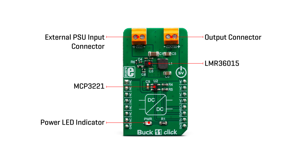
Featuring the HotRod™ technology, the LMR36015 occupies a very small area on the PCB. Combined with the low count of external components it requires, the LMR36015 leaves enough space for an additional IC to be used. This click uses the MCP3221, a 12-bit A/D converter (ADC) which uses the I2C interface, from Microchip. It allows monitoring the output voltage over the I2C interface. This ADC is powered from the +5V mikroBUS™ power rail. The same voltage is used as a reference. The Click board™ itself requires an external power supply to be connected at the input terminal, labeled as VIN. The VOUT terminal provides the connected load with the regulated 3.3V voltage.
Specifications
| Type | Buck |
| Applications | It can be used for a wide range of applications that require 3.3V, including field embedded applications, sensors, PLC modules, video surveillance systems, and similar applications that require step-down voltage conversion. |
| On-board modules | LMR36015, a synchronous step-down converter, from Texas Instruments; MCP3221, a 12-bit A/D converter (ADC) which uses the I2C interface, from Microchip. |
| Key Features | Low power dissipation due to high efficiency, over-current, under-voltage, and thermal protection, wide range for the input supply voltage, ADC for measuring the output voltage accuracy, etc. |
| Interface | I2C |
| Input Voltage | 5V |
| Click board size | M (42.9 x 25.4 mm) |
Pinout Diagram
This table shows how the pinout on Buck 11 click corresponds to the pinout on the mikroBUS™ socket (the latter shown in the two middle columns).
| Notes | Pin | Pin | Notes | ||||
|---|---|---|---|---|---|---|---|
| NC | 1 | AN | PWM | 16 | NC | ||
| NC | 2 | RST | INT | 15 | NC | ||
| NC | 3 | CS | RX | 14 | NC | ||
| NC | 4 | SCK | TX | 13 | NC | ||
| NC | 5 | MISO | SCL | 12 | SCL | I2C Clock | |
| NC | 6 | MOSI | SDA | 11 | SDA | I2C Data | |
| NC | 7 | 3.3V | 5V | 10 | 5V | Power Supply | |
| Ground | GND | 8 | GND | GND | 9 | GND | Ground |
BUCK 11 Click Electrical Specifications
| Description | Min | Typ | Max | Unit |
|---|---|---|---|---|
| Efficiency (5V at VIN, 0.1A to 1.5A) | 83.15 | - | 92.52 | % |
| Efficiency (30V at VIN, 0.1A to 1.5A) | 68.67 | - | 79.52 | % |
| Output voltage (VOUT) | - | 3.3V | - | V |
| Output current (continuous) | 0 | - | 1.5 | A |
Onboard Settings And Indicators
| Label | Name | Default | Description |
|---|---|---|---|
| PWR | PWR | - | Power indication LED |
| VIN | VIN | - | External PSU input connector |
| VOUT | VOUT | - | Output connector |
Software Support
We provide a library for the Buck 11 click on our LibStock page, as well as a demo application (example), developed using MikroElektronika compilers. The demo can run on all the main MikroElektronika development boards.
Library Description
The library allows user to perform the VOUT measurement of the Buck 11 Click board. One measurement cycle can consist a one conversion or more averaged conversions. This library also allows user to enter a real measured reference voltage for the AD conversion (VDD). For more details check documentation.
Key functions:
void buck11_set_vdd_value( float vdd_volts )- This function allows user to set VDD voltage to the desired (measured) value.uint16_t buck11_read_adc( void )- This function reads the results of the AD conversion from the MCP3221A5T 12-bit converter.float buck11_get_vout( uint8_t vout_resolution )- This function allows user to get VOUT voltage value in the desired unit resolution, volts or millivolts.
Examples description
The application is composed of the three sections :
- System Initialization - Initializes peripherals and pins.
- Application Initialization - Initializes I2C serial interface and selects the desired VDD voltage value and VOUT value resolution (to get VOUT value in Volts). Note : The user should measure the VDD voltage value and enter this measured value to the function as VDD value to get more accurate measurement. This VDD voltage is used as reference voltage for the AD conversion.
- Application Task - (code snippet) - Reads the averaged VOUT voltage calculated to Volts by performing a 30 conversions in one measurement cycle. The measured results will be showed on the uart terminal every 300 milliseconds. Note : The input voltage (VIN) range is from 4.2V to 60V. The output current (IOUT) value should not be greater than 1.5A.
void applicationTask()
{
vout_value = buck11_get_averaged_vout( vout_resol, 30 );
FloatToStr( vout_value, text );
floatCut();
mikrobus_logWrite( "** VOUT : ", _LOG_TEXT );
mikrobus_logWrite( text, _LOG_TEXT );
if (vout_resol == _BUCK11_VOUT_VOLTS)
{
mikrobus_logWrite( " V", _LOG_LINE );
}
else
{
mikrobus_logWrite( " mV", _LOG_LINE );
}
mikrobus_logWrite( "*************************************", _LOG_LINE );
Delay_ms( 300 );
}
Additional Functions :
- floatCut - Allows to real values be rounded on two decimal places.
The full application code, and ready to use projects can be found on our LibStock page.
Other mikroE Libraries used in the example:
I2CUARTConversions
Additional notes and informations
Depending on the development board you are using, you may need USB UART click, USB UART 2 click or RS232 click to connect to your PC, for development systems with no UART to USB interface available on the board. The terminal available in all MikroElektronika compilers, or any other terminal application of your choice, can be used to read the message.
MIKROSDK
This click board is supported with mikroSDK - MikroElektronika Software Development Kit. To ensure proper operation of mikroSDK compliant click board demo applications, mikroSDK should be downloaded from the LibStock and installed for the compiler you are using.