
Thermostat 3 Click


- Order number: MIKROE-3724
- Manufacturer product ID: 3724
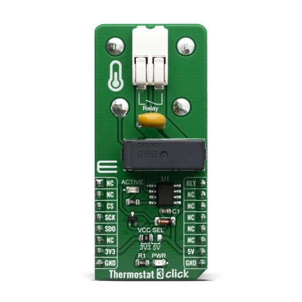
Thermostat 3 Click is a general-purpose thermostat Click board™ designed to be used with any temperature sensor based on the MAX31855 sensor design. The Click board™ is equipped with a 2-pin female socket for thermocouple connection. The K-type thermocouple can be connected directly into the socket, allowing the MAX31855 to take care of the signal-conditioning and output the absolute temperature value. The Click board™ also contains a high-quality relay from Omron, that can be used to open or close an electric circuit. Despite its small size, it can be used with voltage up to 30VDC/220AC and current up to 5A.
Thermostat 3 click is supported by a mikroSDK compliant library, which includes functions that simplify software development. This Click board™ comes as a fully tested product, ready to be used on a system equipped with the mikroBUS™ socket.
The Click board™ is equipped with all the necessary elements, required to provide a reliable operation: it has a varistor across the relay output contacts, preventing excessive voltage transients, it has a flyback diode for the backEMF generated within the relay coil, and a durable mechanical relay, that can withstand up to 20,000,000 mechanical cycles (no load connected). These features allow Thermostat 3 click to be used for a wide range of applications that have to be thermally controlled: various home appliances, air conditioners, cooling fans, small heaters, etc.
HOW DOES IT WORK?
Thermostat 3 click board™ is designed around the MAX31855, as the main IC - a sophisticated thermocouple-to-digital converter with a built-in 14-bit analog-to-digital converter (ADC), from Maxim Integrated. The device also contains cold-junction compensation sensing and correction, a digital controller, a SPI compatible interface, and associated control logic. The Thermostat 3 click is designed to be used with externally connected K-type thermocouple sensor. The communication with the host MCU is performed over the SPI interface, using the dedicated pins of the mikroBUS™.
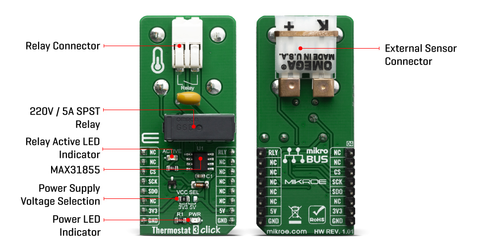
Depending on the temperature information obtained over the SPI interface, the host MCU can take the necessary action: it can either open or close contacts of the relay. The Click board™ uses the G6D series PCB power relay, from Omron. This quality relay can withstand an amazingly large number of mechanical cycles, with no load connected. However, when there is a significant load connected at its output, micro-electric arcs cause the contacts to wear over time. With the maximum load current of 5A, it can sustain up to 70,000 cycles. Its contacts are made of silver alloy, yielding exceptional ON resistance of only 100mΩ (max).
The relay is activated by the host MCU. The voltage for the coil activation is 5V, while the current through the coil is 40mA. The MCU is not able to drive the coil directly, therefore an NPN transistor had to be added. Its base is controlled by the host MCU, allowing the coil to drain enough current from the 5V mikroBUS™ power rail. The base of the transistor is routed to the CS pin of the Click board™. The transistor packs two biasing resistors in the same casing, so it can be directly used on the MCU pin, without external biasing resistors. A red color LED, labeled as ACTIVE is used to indicate that the transistor is in an open state and that the current is running through the relay coil.
When the current through a coil (or any other inductor) is suddenly changed, the backEMF will be generated, opposing the changes of the current. This can sometimes lead to damage to the control circuit: in this case, the transistor will become inversely polarized. To prevent this from happening, a flyback diode is added across the coil. During the normal operation, this diode does not conduct any current. However, when the coil is switched OFF, the inverse polarization will cause the current to pass through this diode with minimum resistance. This prevents inverse (flyback) voltage from building up, so the transistor remains safe.
Contacts at the output may be connected to a higher voltage and larger current may run through. To prevent high voltage transients in this case, a flyback diode is not a viable option. Therefore, Thermostat 3 click uses a varistor (VDR). This component rapidly drops its resistance as the voltage rises above its rated clamping voltage. The excessive voltage transient will pass through the VDR since it will become a current path with the least resistance. During the normal operation, while the voltage stays below the rated clamping voltage, VDR has a very high resistance, so the current runs through the electrical circuit, instead.
The operating voltage of the Click board™ can be selected by the VCC SEL jumper. This jumper allows selecting either 3.3V or 5V from the mikroBUS™. The selected voltage will be applied to the VCC pin of the connected MAX31855 sensor.
SPECIFICATIONS
| Type | Temperature & humidity |
| Applications | Thermostat 3 click can be used for a wide range of applications that have to be thermally controlled: various home appliances, air conditioners, cooling fans, small heaters, etc |
| On-board modules | MAX31855, a sophisticated thermocouple-to-digital converter with a built-in 14-bit analog-to-digital converter (ADC), from Maxim Integrated G6D series PCB power relay, by Omron. |
| Key Features | Built-in 14-bit analog-to-digital converter (ADC), cold-junction compensation sensing and correction, a digital controller, SPI interface, associated control logic. |
| Interface | SPI,GPIO |
| Compatibility | mikroBUS |
| Click board size | L (57.15 x 25.4 mm) |
| Input Voltage | 3.3V,5V |
PINOUT DIAGRAM
This table shows how the pinout on Thermostat 3 click corresponds to the pinout on the mikroBUS™ socket (the latter shown in the two middle columns).
| Notes | Pin | Pin | Notes | ||||
|---|---|---|---|---|---|---|---|
| NC | 1 | AN | PWM | 16 | RLY | Relay Control | |
| NC | 2 | RST | INT | 15 | NC | ||
| Chip Select | CS | 3 | CS | RX | 14 | NC | |
| SPI Clock | SCK | 4 | SCK | TX | 13 | NC | |
| SPI Data Out | SDO | 5 | MISO | SCL | 12 | NC | |
| NC | 6 | MOSI | SDA | 11 | NC | ||
| Power Supply | 3.3V | 7 | 3.3V | 5V | 10 | 5V | Power Supply |
| Ground | GND | 8 | GND | GND | 9 | GND | Ground |
ONBOARD SETTINGS AND INDICATORS
| Label | Name | Default | Description |
|---|---|---|---|
| LD1 | ACTIVE | - | Relay status LED, lights up when the relay is CLOSED |
| LD2 | PWR | - | Power LED indicator |
| CN1 | - | - | Relay output connector |
| CN2 | - | - | External thermocouple connector |
| JP1 | VCC SEL | Left | Power supply voltage selection: left position 3.3V, right position 5V |
SOFTWARE SUPPORT
We provide a library for the Thermostat 3 click on our LibStock page, as well as a demo application (example), developed using MikroElektronika compilers. The demo can run on all the main MikroElektronika development boards.
Library Description
The library initializes and defines the SPI bus driver and drivers that offer a choice for read data form SPI lines. With functions from the library it is possible to read Internal or Thermocouple temperature data in Celsius, Kelvin or Fahrenheit. The library provides full relay control and reads fault error status.
Key functions:
float thermostat3_getInternalTemperature(uint8_t TempIn)- Junction (Internal) Temperaturefloat thermostat3_getThermocoupleTemperature(uint8_t TempIn)- Thermocouple Temperature (K probe)void thermostat3_relayControl(uint8_t relayPos)- Relay Control
Examples description
The application is composed of three sections :
- System Initialization - Initialzes SPI module and all the necessary GPIO pins
- Application Initialization - Initialization driver init
- Application Task - Waits for valid user input and executes functions based on set of valid commands
- Commands : 'e' - Display Thermocouple temperature 'i' - Display Internal temperature 'r' - Relay control (Relay ON / OFF) 'f' - Fault flag (Active ON / OFF) '+' - Change fault flage and display fault status(ERROR / OK)
void applicationTask()
{
uint8_t dataReady_;
char receivedData_;
thermostat3_process();
dataReady_ = UART_Rdy_Ptr();
if (dataReady_ != 0)
{
receivedData_ = UART_Rd_Ptr();
switch (receivedData_)
{
case 'i' :
{
InternalTemp = thermostat3_getInternalTemperature(_THERMOSTAT3_TEMP_IN_CELSIUS);
FloatToStr(InternalTemp, demoText);
mikrobus_logWrite("# Internal Temperature: ", _LOG_TEXT);
mikrobus_logWrite(demoText, _LOG_LINE);
break;
}
case 'e' :
{
ThermocoupleTemp = thermostat3_getThermocoupleTemperature(_THERMOSTAT3_TEMP_IN_CELSIUS);
FloatToStr(ThermocoupleTemp, demoText);
mikrobus_logWrite("# Thermocouple Temperature: ", _LOG_TEXT);
mikrobus_logWrite(demoText, _LOG_LINE);
break;
}
case 'r' :
{
if(_relayFlag == 1)
{
_relayFlag = 0;
thermostat3_relayControl(_THERMOSTAT3_RELAY_OFF);
mikrobus_logWrite("# Relay OFF", _LOG_LINE);
}
else
{
_relayFlag = 1;
thermostat3_relayControl(_THERMOSTAT3_RELAY_ON);
mikrobus_logWrite("# Relay ON", _LOG_LINE);
}
break;
}
case 'f' :
{
if(_faultFlag == 1)
{
_faultFlag = 0;
mikrobus_logWrite("# Fault status -- OFF", _LOG_LINE);
}
else
{
_faultFlag = 1;
mikrobus_logWrite("# Fault status -- ON", _LOG_LINE);
}
break;
}
case '+' :
{
if(_faultFlag == 1)
{
_fError++;
if(_fError > 3)
{
_fError = 0;
}
_displayFault(_fError);
_faultStatus = thermostat3_getFaultData(0x01 << _fError);
if (_faultStatus == 1 )
{
mikrobus_logWrite(" -- ERROR", _LOG_LINE);
}
else
{
mikrobus_logWrite(" -- OK", _LOG_LINE);
}
}
else
{
mikrobus_logWrite(" Fault status is OFF, Please turn ON fault status!!!", _LOG_LINE);
}
break;
}
}
}
}
Additional Functions :
- void _displayFault( ) - Display fault
The full application code, and ready to use projects can be found on our LibStock page.
Other mikroE Libraries used in the example:
- SPI Library
- UART Library
- Conversions
Additional notes and informations
Depending on the development board you are using, you may need USB UART click, USB UART 2 click or RS232 click to connect to your PC, for development systems with no UART to USB interface available on the board. The terminal available in all MikroElektronika compilers, or any other terminal application of your choice, can be used to read the message.
MIKROSDK
This Click board™ is supported with mikroSDK - MikroElektronika Software Development Kit. To ensure proper operation of mikroSDK compliant Click board™ demo applications, mikroSDK should be downloaded from the LibStock and installed for the compiler you are using.
For more information about mikroSDK, visit the official page.