
IrDA 3 click


Prices incl. VAT plus shipping costs
Ready to ship today,
Delivery time appr. 1-3 workdays
- Order number: MIKROE-2871
- Manufacturer product ID: 2871
IrDA 3 click is an intelligent IR transceiver device that can both send and receive UART commands via the IR interface. IrDA 3 click features both the IR transceiver and the encoder/decoder IC, used to convert the UART data and send or receive it in IrDA® compatible format. IrDA 3 click also has an onboard clock generator for the fastest possible UART performance of 115,200 bps, so it does not need an additional clock signal to be generated by the MCU.
IrDA 3 click provides a direct and easy to use UART to IrDA interface. The device can be used for various applications that use the short-range remote communication, such as fax machines, photocopiers, screen projectors, TV boxes, Data loggers, GPS, various system controllers and many other IRDA standard compatible applications.
HOW DOES IT WORK?
IrDA 3 click is composed of two integrated devices. The first one is the TFDU4101 transceiver from Vishay, an infrared transceiver module compliant to the latest IrDA® physical layer standard. It supports IrDA speeds up to 115.2 Kbps. The transceiver module is composed of the IRED (infrared emitter) and the photodiode IR receiver, which is used to both emit and receive the IR light commands. The range of this device is more than 1m and it depends on several factors. To ensure maximum possible range, the power supply is decoupled with proper capacitors, also the used oscillator is very stable and accurate, resulting with the range of about 4m.
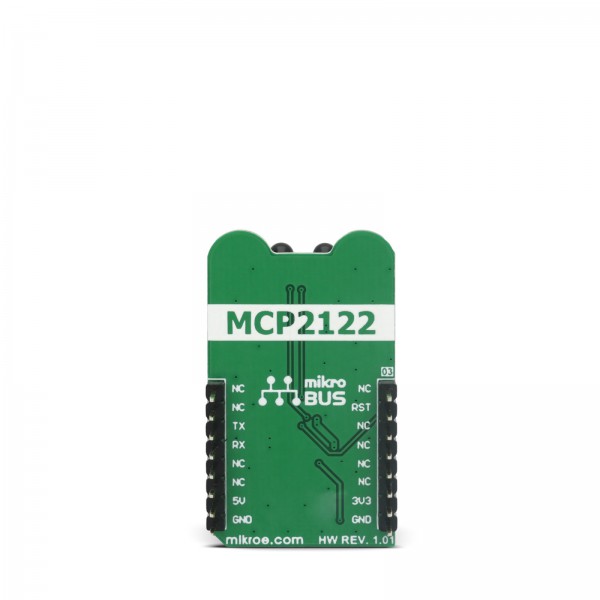
The second IC device is the MCP2122, an infrared half duplex encoder/decoder from Microchip that takes care of the proper conversion of the UART signals to TFDU4101 acceptable IrDA standard compliant data format. The MCP2122 has its UART interface pins routed to the mikroBUS™, and IrDA interface pins routed to the TFDU4101 IrDA module. The maximum communication speed for the UART interface is determined by the onboard oscillator that works at 1.8432MHz. The MCP2122 has the 16XCLK input that acts as a bit clock. The state of the bit is determined within 16 clock cycles of the 16XCLK input. This means that for every bit of the UART information, 16-bit clock cycles are needed - so the UART frequency is the bit clock frequency divided by 16, as shown by this formula: 1,843,200 / 16 = 115,200. At the same time, 115,200 is the maximum baud rate that can be used for the TFDU4101 IrDA transceiver.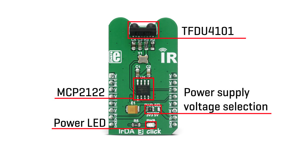
The click also has a voltage selection jumper for selecting the voltage between 3.3V and 5V. Besides the UART RX and UART TX signals routed to the mikroBUS™, it also has the RESET signal routed to the RST pin of the mikroBUS™. The RESET pin is used to reset the MCP2122 device. The LOW logic state on this pin will reset the device, while the HIGH state is used for a normal operation. The device can be put in a low power state if the RST pin is held LOW. Working with this click board is easy and the demo application that comes with the click board™ can be used as a reference for future designs. Besides the demo application example, the library provides functions for simplified workflow with the IrDA 3 click.
SPECIFICATIONS
PINOUT DIAGRAM
This table shows how the pinout on IrDA 3 click corresponds to the pinout on the mikroBUS™ socket (the latter shown in the two middle columns).
| Notes | Pin | Pin | Notes | ||||
|---|---|---|---|---|---|---|---|
| NC | 1 | AN | PWM | 16 | NC | ||
| Reset | RST | 2 | RST | INT | 15 | NC | |
| NC | 3 | CS | RX | 14 | TX | UART Transmit | |
| NC | 4 | SCK | TX | 13 | RX | UART Receive | |
| NC | 5 | MISO | SCL | 12 | NC | ||
| NC | 6 | MOSI | SDA | 11 | NC | ||
| Power Supply | +3.3V | 7 | 3.3V | 5V | 10 | +5V | Power Supply |
| Ground | GND | 8 | GND | GND | 9 | GND | Ground |
IRDA 3 CLICK ELECTRICAL SPECIFICATIONS
| Description | Min | Typ | Max | Unit |
|---|---|---|---|---|
| Input logic LOW level voltage | GND | 0.2 x VCC | V | |
| Input logic HIGH level voltage | 0.8 x VCC | VCC | V | |
| UART baud rate | 115,200 | bps |
ONBOARD SETTINGS AND INDICATORS
| Label | Name | Default | Description |
|---|---|---|---|
| LD1 | PWR | - | Power LED indicator |
| JP1 | PWR SEL | Left | Power supply voltage selection: left position 3V3, right position 5V |
SOFTWARE SUPPORT
We provide a library for IrDA 3 click on our LibStock page, as well as a demo application (example), developed using MikroElektronika compilers and mikroSDK. The provided click library is mikroSDK standard compliant. The demo application can run on all the main MikroElektronika development boards.
Library description
The library contains functions that perform UART reading and writing.
Key functions:
void irda3_writeByte(uint8_t input); - Function writes (sends) one byte to the UART RX buffer
uint8_t irda3_readByte(); - Function reads (receives) one byte from the UART RX buffer
uint8_t irda3_byteReady(); - Function checks state of the RX buffer (new data is placed in)
void irda3_reset(); - Function resets the and sets back in normal operating mode
Example description
- System Initialization - Initializes peripherals and pins.
- Application Initialization - Initializes click driver.
- Application Task - Checks if new data byte has been received in the RX buffer (ready for reading), and if ready than reads one byte from the RX buffer. In second case application task writes message data via UART and IR interface.
void applicationTask()
{
uint8_t tmp;
uint8_t rdyFlag;
// RECEIVER - UART polling
#ifdef __RX__
rdyFlag = irda3_byteReady();
if (1 == rdyFlag)
{
tmp = irda3_readByte();
mikrobus_logWrite( &tmp, _LOG_BYTE );
}
#endif
// TRANSMITER - TX each 2 sec
#ifdef __TX__
for (tmp = 0; tmp < 9; tmp++)
{
irda3_writeByte( MESSAGE_DATA[tmp] );
mikrobus_logWrite( "MESSAGE SENT", _LOG_LINE );
}
Delay_ms(2000);
#endif
}
The full application code, and ready to use projects can be found on our LibStock page.
Additional notes and information
Depending on the development board you are using, you may need USB UART click, USB UART 2 click or RS232 click to connect to your PC, for development systems with no UART to USB interface available on the board. The terminal available in all MikroElektronika compilers, or any other terminal application of your choice, can be used to read the message.
MIKROSDK
This click board is supported with mikroSDK - MikroElektronika Software Development Kit. To ensure proper operation of mikroSDK compliant click board demo applications, mikroSDK should be downloaded from the LibStock and installed for the compiler you are using.
For more information about mikroSDK, visit the official page.