
LoRa 4 click


Prices incl. VAT plus shipping costs
Ready to ship today,
Delivery time appr. 1-3 workdays
- Order number: MIKROE-2934
- Manufacturer product ID: MIKROE-2934
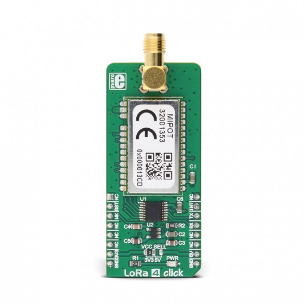
LoRa 4 click is a LoRa RF technology based SRD transceiver, which operates at a sub-gigahertz frequency of 868MHz. Thanks to the spread spectrum modulation feature, as well as the low power consumption, it is capable of achieving a long-range LPWAN communication, immune to interferences. This click board™ features an embedded LoRaWAN™ Class A and Class C compliant stack. The transceiver is RED 2014/53/EU certified and compliant to REACH and RoHS regulations, allowing for an easy integration into the final application, reducing development time, costs, and time to market.
Equipped with both LoRaWAN Class A and Class C compliant stacks, LoRa 4 click offers an easy and reliable solution for developing low power, highly integrated LoRaWAN IoT networks, security systems, alarm networks, and similar applications that require simple and reliable networking solutions.
HOW DOES IT WORK?
The main active element of the LoRa 4 click is a wireless transceiver module from Mipot company, labeled as 32001353. It is the LoRa RF technology-based long-range transceiver, featuring the LoRaWAN protocol, optimized for a robust LoRaWAN networking, immune to interferences.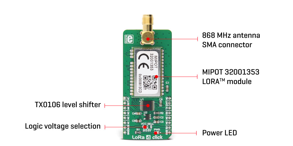
The LoRaWAN network is sorted into three different classes. Class A compliant devices network is a network where end nodes are battery operated, the communication payload is small with longer intervals, and the communication is initiated by the end node (uplink). Communication is bidirectional, and the server responds in predetermined response windows. In a Class C network, the communication is bidirectional and the server is able to initiate the communication at any time. This type of network requires more power for the end nodes, compared to Class A, as they have to stay active all the time. Also, Class C has almost no latency between the server and the end node, at all.
Unlike LoRa 3 click, which can establish a peer-to-peer communication, LoRa 4 click requires a LoRaWAN concentrator/gateway.To join a LoRaWAN network, the endpoint device has to use a unique endpoint address, an application session key, and network session key. The first method is called over-the-air activation (OTAA), where these keys are issued after a specific join procedure (more info can be found in the LoRaWAN specification). The second method is to assign these keys manually, using UART commands. This method is called activation by personalization (ABP) and can be prone to some security issues. In any case, before an end-device can communicate on the LoRaWAN network, it must be activated.
The communication is done via the UART interface. A communication between the module and the host MCU starts with the MCU pulling the NWAKE pin to a LOW logic state. This will wake up the module, after which the module expects the 0xAA code. This code is a header of every data packet that has been sent or received. After the header, a command code is sent, followed by the payload and the checksum. After a complete packet has been received and its checksum is verified, the module pulls the NDATA_INDICATE (ND_IND) to a LOW logic level. After a short timeout, the data (message) is sent via the UART TX pin of the module, back to the host MCU. At the end of the communication cycle, the ND_IND pin is pulled to a HIGH logic level and the module goes into the sleep mode, waiting to be awakened again by the NWAKE pin. Every command from the host results with a response from the module in the same format, with the command code ORed with 0x80.
To allow interfacing with both 3.3V and 5V MCUs, this click board™ employs the TXB0106, a bidirectional level shifter and voltage translator from Texas Instruments, supported by a 3.3V LDO. This translates the external voltage levels to acceptable levels that can be used on the Mipot LoRa module. All the I/O pins of the 32001353 LoRa module are routed via this IC to the mikroBUS™ pins.
The NWAKE pin from the 32001353 LoRa module is routed to the mikroBUS™ CS pin, while the UART RX and TX pins are routed to the appropriate mikroBUS™ UART pins, via the level shifter. ND_IND pin is routed to the INT pin of the mikroBUS™ - also via the level shifter - so it can be used to easily trigger an interrupt, or some other type of alert indicating that the module transmits data.
The NRST pin is routed to the mikroBUS™ RST pin and it is used to reset the device. It is internally pulled up with a resistor.
The provided LoRa 4 click library offers easy to use functions, which simplify configuration and communication tasks. Their usage is demonstrated in the included example application.
LoRa 4 click board is equipped with an SMA connector so it can be equipped with the appropriate 868MHz antenna. The onboard SMD jumper labeled as VCC SEL is used to select the voltage input for the level shifter for interfacing with 3.3V or 5V MCUs.
SPECIFICATIONS
| Type | LoRa |
| Applications | LoRa 4 click offers an easy and reliable solution for developing low power, highly integrated IoT networks, security systems, alarm networks, and similar applications that require simple and reliable networking solutions |
| On-board modules | MIPOT 32001353 LoRaWAN 868 MHz band TRX module |
| Radio Region | Europe |
| Key Features | The click board™ features robust Lora RF technology based wireless networking, LoraWAN protocol, easy to use UART interface and low power consumption |
| Interface | UART |
| Compatibility | mikroBUS |
| Click board size | L (57.15 x 25.4 mm) |
| Input Voltage | 3.3V or 5V |
PINOUT DIAGRAM
This table shows how the pinout on LoRa 4 click corresponds to the pinout on the mikroBUS™ socket (the latter shown in the two middle columns).
| Notes | Pin | Pin | Notes | ||||
|---|---|---|---|---|---|---|---|
| NC | 1 | AN | PWM | 16 | NC | ||
| Reset | RST | 2 | RST | INT | 15 | INT | Data TX indication |
| Wake up | WK | 3 | CS | RX | 14 | TX | UART transmit |
| NC | 4 | SCK | TX | 13 | RX | UART receive | |
| NC | 5 | MISO | SCL | 12 | NC | ||
| NC | 6 | MOSI | SDA | 11 | NC | ||
| Power supply | +3.3V | 7 | 3.3V | 5V | 10 | +5V | Power supply |
| Ground | GND | 8 | GND | GND | 9 | GND | Ground |
LORA 4 CLICK ELECTRICAL SPECIFICATIONS
| Description | Min | Typ | Max | Unit |
|---|---|---|---|---|
| Operating Frequency Range | 863 | 870 | MHz | |
| UART interface baud rate | 115.2 | kbps |
ONBOARD SETTINGS AND INDICATORS
| Label | Name | Default | Description |
|---|---|---|---|
| JP1 | PWR.SEL | Left | Logic level voltage selection: Left position 3V3, right position 5V |
| LD1 | PWR | - | Power LED indicator |
SOFTWARE SUPPORT
We provide a library for LoRa 4 click on our LibStock page, as well as a demo application (example), developed using MikroElektronika compilers and mikroSDK. The provided click library is mikroSDK standard compliant. The demo application can run on all the main MikroElektronika development boards.
Library Description
Initializes and defines UART bus driver and driver functions which offers a choice to writing on EEPROM, reading from EEPROM, communication with other LoRa Mipot 32001353 click, but first, we must join to network and a router is needed. Functions also offer a choice to setting and getting channel parameters and getting indications on some executed commands. For more details check the documentation.
Key functions :
void lora4_process() - The function executes reading indications and forwards indications to the handler.
LORA4_RETVAL_T lora4_writeEeprom( uint8_t address, uint8_t nBytes, uint8_t *dataIn ) - The function writes data to EEPROM.
LORA4_RETVAL_T lora4_joinNetwork( uint8_t mode ) - The function performs the join network command.
LORA4_RETVAL_T lora4_txMessage( uint8_t *dataIn, uint8_t nBytes, uint8_t port, uint8_t option ) - The function performs the transmission of the radio frame.
LORA4_RETVAL_T lora4_setChannel( uint8_t index, uint32_t freq, uint8_t dataRateRange, uint8_t status ) - The function sets channel parameters and enables/disables optional channels.
Examples Description
The application is composed of three sections:
- System Initialization - Initializes peripherals and pins.
- Application Initialization - Initializes UART bus driver, sets indication handler, sets channel parameters, joins the network and performs the transmission of the radio frame.
- Application Task - (code snippet) - Checks is indication occurred.
void applicationTask()
{
lora4_process();
}
Additional Functions:
void indicationHandler( uint8_t *cmd, uint8_t *plSize, uint8_t *plBuffer ) - Logs results on USB UART when device gets indication on command.
Other mikroE Libraries used in the example:
- Conversions
- UART
Additional notes and information
Depending on the development board you are using, you may need USB UART click, USB UART 2 click or RS232 click to connect to your PC, for development systems with no UART to USB interface available on the board. The terminal available in all MikroElektronika compilers, or any other terminal application of your choice, can be used to read the message.
MIKROSDK
This click board is supported withmikroSDK - MikroElektronika Software Development Kit. To ensure proper operation of mikroSDK compliant click board demo applications, mikroSDK should be downloaded from the LibStock and installed for the compiler you are using.
For more information about mikroSDK, visit the official page.