
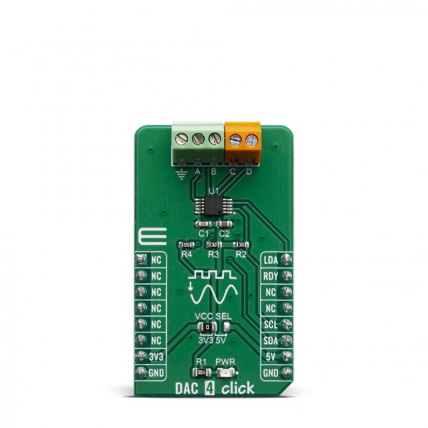
DAC 4 Click


- Order number: MIKROE-3707
- Manufacturer product ID: 3707
DAC 4 Click carries Microchip’s MCP4728 IC, a Quad Digital-to-Analog Converter with nonvolatile (EEPROM) Memory. The digital value is converted to the appropriate voltage level in the range between GND and VCC, which is proportional to the received 12-bit number. MCP4726 also integrates EEPROM for storing DAC register and configuration bit values. These options give a lot of flexibility which make it a perfect choice for an accurate and simple generation of analog signals for various purposes, such as PLC/DCS modules, temperature and pressure control, medical and scientific instrumentation, chromatography and other similar applications, where accurate digital to analog conversion is needed.
DAC 4 click board™ is supported by a mikroSDK compliant library, which includes functions that simplify software development. This Click board™ comes as a fully tested product, ready to be used on a system equipped with the mikroBUS™ socket.
DAC 4 click is an advanced 12bit multichannel digital to analog converter (DAC), with 4 single-ended/pseudo differential outputs. The click board™ has configurable internal voltage, which allows for unrestrained configuration of the device. DAC 4 click can be used for an digital to analog conversion in various applications, such as temperature and pressure control, medical and scientific instrumentation, chromatography and other similar applications, where accurate digital to analog conversion is needed.
HOW DOES IT WORK?
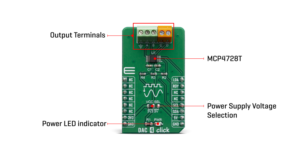
The main active component of the DAC 4 click is the MCP4728, a quad, 12-bit voltage output Digital-to-Analog Convertor (DAC) with nonvolatile memory (EEPROM), from Microchip. Its on-board precision output amplifier allows it to achieve rail-to-rail analog output swing. The DAC input codes, device configuration bits, and I2C address bits are programmable to the nonvolatile memory (EEPROM) by using I2C serial interface commands. The nonvolatile memory feature enables the DAC device to hold the DAC input codes during power-off time, allowing the DAC outputs to be available immediately after power-up with the saved settings.
The MCP4728 device has a high precision internal voltage reference (VREF = 2.048V). The internal reference can be selected by user, or external reference may be used (VDD) for each channel individually. This gives the ADC 4 click good flexibility for use in various applications.
Each channel can be operated in Normal mode or Power-Down mode individually by setting the configuration register bits. In Power-Down mode, most of the internal circuits in the powered down channel are turned off for power savings, and the output amplifier can be configured to present a known low, medium, or high resistance output load. This device also includes a Power-on Reset (POR) circuit to ensure reliable power-up and an on-board charge pump for the EEPROM programming voltage.
The MCP4728 has four output pins, which are routed to the output terminal blocks (TB1 and TB2). The output range of the DAC is 0 V to VREF or 0 V to 2×V REF. The communication with the main MCU is established over a two-wire I2C compatible serial interface, with standard (100 kHz), fast (400 kHz), or high speed (3.4 MHz) modes supported. The I2C lines (SCL and SDA) are routed to the dedicated mikroBUS™pins. The LDA pin is multipurpose GPIO: It can be used as Synchronization input or for the device I2C address selection. RDY pin can also optionaly be used to monitor status of EEPROM programming activity.
The voltage level of the logic section can be selected via the VCCSEL jumper, between 3.3V and 5V. This allows for both 3.3V and 5V capable MCUs to use the I2C communication lines properly.
SPECIFICATIONS
| Type | DAC |
| Applications | Suitable for , temperature and pressure control, medical and scientific instrumentation, chromatography and other similar applications, where accurate digital to analog conversion is needed. |
| On-board modules | MCP4728, a quad, 12-bit voltage output Digital-to-Analog Convertor (DAC) with nonvolatile memory (EEPROM), from Microchip. |
| Key Features | high precision internal voltage reference, Low Power Consumption, each channel separately configurable, power-on reset (POR) circuit, high speed I2C serial interface (up to 3.4 MHz), fast settling time |
| Interface | GPIO,I2C |
| Click board size | M (42.9 x 25.4 mm) |
| Input Voltage | 3.3V or 5V |
PINOUT DIAGRAM
This table shows how the pinout on DAC 4 click corresponds to the pinout on the mikroBUS™ socket (the latter shown in the two middle columns).
| Notes | Pin | Pin | Notes | ||||
|---|---|---|---|---|---|---|---|
| NC | 1 | AN | PWM | 16 | LDA | Multipurpose GPIO | |
| NC | 2 | RST | INT | 15 | RDY | Ready Out | |
| NC | 3 | CS | RX | 14 | NC | ||
| NC | 4 | SCK | TX | 13 | NC | ||
| NC | 5 | MISO | SCL | 12 | SCL | I2C serial clock | |
| NC | 6 | MOSI | SDA | 11 | SDA | I2C serial data | |
| Power Supply | 3.3V | 7 | 3.3V | 5V | 10 | 5V | Power supply |
| Ground | GND | 8 | GND | GND | 9 | GND | Ground |
ONBOARD SETTINGS AND INDICATORS
| Label | Name | Default | Description |
|---|---|---|---|
| LD1 | PWR | - | Power LED Indicator |
| JP1 | VCC SEL | Left | Logic level selection, left position 3.3V, right 5V |
DAC 4 CLICK ELECTRICAL SPECIFICATIONS
| Description | Min | Typ | Max | Unit |
|---|---|---|---|---|
| Analog output voltage | 0 | 5 | V | |
| Settling Time | - | 6 | - | μs |
| Sampling bit depth | - | 12 | - | bits |
| Operating supply voltage | 2.7 | 3.3 | 5.5 | V |
SOFTWARE SUPPORT
We provide a library for the DAC 4 click on our LibStock page, as well as a demo application (example), developed using MikroElektronika compilers. The demo can run on all the main MikroElektronika development boards.
Library Description
Library contains function for getting INT pin state Library contains function for setting PWM pin state Library contains function for getting data via I2C Library contains function for setting data via I2C Library contains functions for executing general call functions (reset, wake up and software update) Library contains functions for executing fast write, multi write, sequential write and single write commands Library contains functions for setting voltage reference, power mode and gain Library contains function for getting channel reports.
Key functions:
uint8_t dac4_general_call_reset( void )- This function executes general call reset command.uint8_t dac4_single_write( T_dac_channel_setting * channel_X )- This function executes single write command.uint8_t dac4_data_report( T_dac_channel_setting * channel_buffer )- This function reads data for all 4 channels, forms a report and stores it into the buffer.
Examples description
The application is composed of three sections :
- System Initialization - Initializes GPIO pins, I2C and LOG modules
- Application Initialization - Initializes I2C driver, executes general call reset and wake up commands and initializes variables to zero
- Application Task - Waits for user input and based on it logs reports or sets output value for specified channel
void applicationTask( )
{
dac4_check_input( );
if (message_ok_flag == 1)
{
dac4_parse_message( );
message_ok_flag = 0;
}
}
Additional Functions :
- dac4_receive_char() - receives single character from UART terminal and stores it into the buffer
- dac4_check_input() - calls dac4_receive_char() function to fill the buffer and checks if received character is correct
- dac4_log_report() - logs channel reports
- dac4_set_output() - sets output channel values
- dac4_parse_message() - parses message stored into the buffer and calls appropriate functions
The full application code, and ready to use projects can be found on our LibStock page.
Other mikroE Libraries used in the example:
- I2C
- UART
- Conversions
Additional notes and informations
Depending on the development board you are using, you may need USB UART click, USB UART 2 click or RS232 click to connect to your PC, for development systems with no UART to USB interface available on the board. The terminal available in all MikroElektronika compilers, or any other terminal application of your choice, can be used to read the message.
MIKROSDK
This Click board™ is supported with mikroSDK - MikroElektronika Software Development Kit. To ensure proper operation of mikroSDK compliant Click board™ demo applications, mikroSDK should be downloaded from the LibStock and installed for the compiler you are using.
For more information about mikroSDK, visit the official page.