
STSPIN220 click


- Order number: MIKROE-3545
- Manufacturer product ID: 3545
STSPIN220 click is a stepper motor driver with the PWM current control and selectable microstepping up to 256 microsteps. It is based on the STSPIN220, a low voltage stepper motor driver from STSPIN2 series. It is optimized for battery-powered, low voltage motor driving applications, featuring the lowest standby current available on the market (max 80 nA). The STSPIN220 is a high-efficiency motor driver, featuring low ON resistance MOSFETs as the output stage, in a small 3x3mm QFN package. Its output stage implements the PWM current control with fixed OFF time, along with a full set of protection features. The device can be used with the step motor voltage ranging from 1.8V to 10V, and current up to 1.3A per bridge.
STSPIN220 click is supported by a mikroSDK compliant library, which includes functions that simplify software development. This Click board™ comes as a fully tested product, ready to be used on a system equipped with the mikroBUS™ socket.
This Click board™ is optimized for driving bipolar stepper motors in portable applications. Therefore, the STSPIN220 integrates very efficient H-Bridges with ON resistance of approximately 400mΩ (HS+LS) across each bridge. Motor current can be limited by an onboard potentiometer. These features make STSPIN220 click perfectly suited for rapid development of various battery-powered stepper motor applications, including camera movable parts, toys, portable printers, mechatronics, robotics-related applications, etc.
HOW DOES IT WORK?
STSPIN220 click is based on the STSPIN220, a low voltage stepper motor driver by STMicroelectronics. The monolithic IC incorporates both the power MOSFETs and the logic circuitry necessary for simplified control and reliable functioning of the connected bipolar stepper motor. Featuring a microstepping sequencer that supports up to 256 microsteps, this IC can perform very smooth and silent movements. The step sequencer also controls the VREF voltage, allowing the current through coils to be at an optimal level during the microstepping. In full step mode, the maximum current through the coils is controlled by the VREF, according to the formula given below. As the sequencer propagates through the microsteps, the VREF is further reduced following a circular pattern, ensuring maximum power efficiency for each step.
The STSPIN220 is targeted towards low-voltage and battery-powered applications, featuring optimizations such as zero-consumption state, in order to guarantee lowered power consumption. It has two PWM current controllers with the fixed OFF time for each H-Bridge, during which the current decay sequence is performed. This effectively limits the maximum current through the connected motor phase. The OFF (decay) time is fixed to approximately 40 µs on this Click board™. It is also divided into slow decaying and fast decaying segments. The slow decay segment lasts for 5/8 of the total OFF time, while the fast decay segment lasts for 3/8 of the total OFF time.
The PWM current controller compares the voltage across two sense resistors (VSENS1, and VSENS2) and the VREF voltage, which can be adjusted by a potentiometer. When VSENS becomes greater than the VREF voltage, the current limiting is triggered, and the OFF timer starts counting. The decay sequence is performed. By using a simple formula, the VREF voltage can be determined for a specific load current:
VREF = RSENS · ILOAD
Where:
- VREF is the voltage on the REF pin of the STSPIN220, adjustable with the potentiometer;
- RSENS is the resistance of the current sensing resistor, which is 330 mΩ;
- ILOAD is the peak current through the motor coils;
By knowing the RSENS, it can be easily calculated how much voltage should be applied to the REF pin of the STSPIN220, to limit the current according to ILOAD. For example, if there is 0.423V applied at the VREF pin, the current limit will be maxed out to 1.28A. The potentiometer allows to simply adjust the VREF voltage, according to needs.
The STSPIN220 contains two independent H-Bridges, and each of them controls one phase of the bipolar stepper motor. The motor can be controlled by using these pins: DIR/MODE4, STCK/MODE3, RST, EN, and FAULT.
The DIR/MODE4 pin determines the direction of the rotation. If set to a HIGH logic level, the internal microstepping counter will increase its value with each pulse coming through the STCK/MODE 3 pin. The LOW logic level on this pin will cause the microstepping sequencer to decrease its counter. DIR/MODE 4 pin is routed both to the mikroBUS™ pin AN (labeled as DIR), and a DIP switch on the board, labeled as SW4. The DIP switch is used for its secondary function. The secondary function is a selection of the step size, along with three more DIP switches located on the Click board™ (SW1 to SW4).
STCK/MODE 3 pin has already been explained above: a pulse on this pin will cause the microstepping sequencer to increase or decrease its counter, depending on the state of the DIR pin. Besides the PWM pin on the mikroBUS™, it is also routed to the SW3 DIP switch, and it is used for the selection of the step size.
SW1 and SW2 switches on the Click board™ are also used to determine the step size. All the SW dip switches are latched during power-up or after the device reset. SW1 and SW2 switches have an override functionality: they can immediately set the stepping mode to full step if both set to a LOW logic level. This can be useful in situations where fast movement is required (i.e. the home position of the printer). More information about the microstepping mode selection can be found in the datasheet of the STSPIN220 IC.
The STBY/RESET (RST) pin of the STSPIN220 is used to set both bridge outputs in HIGH-Z mod, disconnecting the power supply from the H-Bridges. This pin allows lower average power consumption as no current can flow from the power supply to the motor. This pin is routed to the RST pin of the mikroBUS™.
The EN/FAULT (EN) pin has a double purpose: when set to a high logic level, it acts as a chip enable, allowing the device to operate. In the case of a fault condition on the IC, it will be asserted to a LOW logic level, acting as an interrupt pin. After a timeout period defined by the external capacitor and resistor values, a restart attempt will be made. This pin is routed to both CS and INT pin of the mikroBUS™, allowing the host MCU to use both functions. These pins are labeled as EN and FLT on the Click board™, respectively.
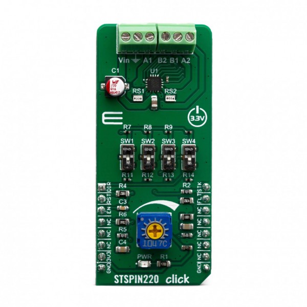
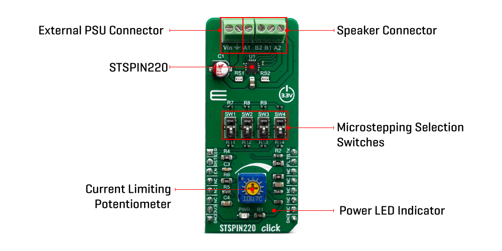
The motor power supply can be connected to the input terminal labeled as VIN and should be within the range of 1.8V to 10V. Stepper motor coils can be connected to the terminals labeled as A1, B2, B1, and A2. The Click board™ requires an external power supply for the motor in order to work. However, it also requires 3.3V from the mikroBUS™ rail.
SPECIFICATIONS
| Type | Stepper |
| Applications | Perfectly suited for rapid development of various battery-powered stepper motor applications, including camera movable parts, toys, portable printers, mechatronics, robotics-related applications, etc. |
| On-board modules | STSPIN220, a stepper motor driver with integrated 256-steps control logic, by STMicroelectronics. |
| Key Features | Integrated current sensing, high efficiency, overcurrent, thermal and undervoltage with fault indication pin, simple motor control interface, up to 1:256 microstepping, adjustable current limiting, selectable step size, and more. |
| Interface | GPIO |
| Click board size | M (42.9 x 25.4 mm) |
| Input Voltage | 3.3V |
PINOUT DIAGRAM
This table shows how the pinout on STSPIN220 click corresponds to the pinout on the mikroBUS™ socket (the latter shown in the two middle columns).
| Notes | Pin | Pin | Notes | ||||
|---|---|---|---|---|---|---|---|
| Direction Control | DIR | 1 | AN | PWM | 16 | STK | Step Control |
| Chip Reset | RST | 2 | RST | INT | 15 | FLT | Fault Reporting |
| Chip Enable | EN | 3 | CS | RX | 14 | NC | |
| NC | 4 | SCK | TX | 13 | NC | ||
| NC | 5 | MISO | SCL | 12 | NC | ||
| NC | 6 | MOSI | SDA | 11 | NC | ||
| Power Supply | 3.3V | 7 | 3.3V | 5V | 10 | NC | |
| Ground | GND | 8 | GND | GND | 9 | GND | Ground |
ONBOARD SETTINGS AND INDICATORS
| Label | Name | Default | Description |
|---|---|---|---|
| PWR | PWR | - | Power LED Indicator |
| SW1 - SW4 | SW1 - SW4 | Up | Microstepping selection switches |
| VR1 | - | - | Potentiometer for current limiting |
SOFTWARE SUPPORT
We provide a library for the STSPIN220 click on our LibStock page, as well as a demo application (example), developed using MikroElektronika compilers. The demo can run on all the main MikroElektronika development boards.
Library Description
Library carries everything needed for stepper motor control including speed and acceleration setup. Library is also adjustable to working on different amount of ticks per second, also speed and acceleration can be provided in float format. Buffer used for movement calculation is defined by user so this library can be adjusted for MCUs with very limited RAM resources. Check documentation for more details how to use it.
Key functions:
- uint8_t stspin220_setSpeed( float minSpeed, float maxSpeed, float accelRatio, T_STSPIN220_OBJ obj ) - Setup motor speed.
- uint8_t stspin220_setRoute( const uint8_t direction, uint32_t steps, T_STSPIN220_OBJ obj ) - Setup new route.
- void stspin220_start( T_STSPIN220_OBJ obj ) - Start motor movement.
Examples description
The application is composed of the three sections :
- System Initialization - Initializes all GPIO pins found on STSPIN220 Click and timer to 1ms interrupt.
- Application Initialization - First segment initializes driver and stepper control. Second segment setup movement limits, maximum and minimum speed, and acceleration ratio. Third segment enables motor and setup new route which will be called from application task.
- Application Task - (code snippet) - Sequentialy moves motor. First part of sequence executes movement until the end. Second part stop motor movement after one second and continues sequence after two seconds.
void applicationTask()
{
stspin220_start( (T_STSPIN220_OBJ)&myStepper );
while ( myStepper.status.running )
{
stspin220_process( (T_STSPIN220_OBJ)&myStepper );
}
Delay_ms( 2000 );
stspin220_start( (T_STSPIN220_OBJ)&myStepper );
Delay_ms( 1000 );
stspin220_stop( (T_STSPIN220_OBJ)&myStepper );
Delay_ms( 2000 );
}
In addition to library function calls example carries necessay Timer ISR and Timer initialization. Check Timer initialization setings and update it according to your MCU - Timer Calculator.
The full application code, and ready to use projects can be found on our LibStock page.
Additional notes and informations
Depending on the development board you are using, you may need USB UART click, USB UART 2 click or RS232 click to connect to your PC, for development systems with no UART to USB interface available on the board. The terminal available in all MikroElektronika compilers, or any other terminal application of your choice, can be used to read the message.
MIKROSDK
This click board is supported with mikroSDK - MikroElektronika Software Development Kit. To ensure proper operation of mikroSDK compliant click board demo applications, mikroSDK should be downloaded from the LibStock and installed for the compiler you are using.
For more information about mikroSDK, visit the official page.