
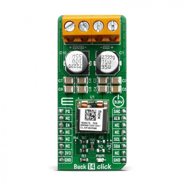
Buck 14 Click


- Order number: MIKROE-3847
- Manufacturer product ID: 3847
The Buck 14 Click is a Click board™ based around the BMR4613001/001, a PoL regulator from Flex. It's high-efficiency step-down converter which provides a highly regulated output voltage derived from the connected power source, rated from 4.5 to 14V. The regulated output voltage can be selected between 0.6V and 5V. The Buck 14 click due to high efficiency of BMR4613001/001 allows the Click board™ to easily deliver up to 12A of current with maximum of 60W of power and high efficiency, typ. 96 % at 12Vin, 5Vout and 80% load.
The Buck 14 click is supported by a mikroSDK compliant library, which includes functions that simplify software development. This Click board™ comes as a fully tested product, ready to be used on a system equipped with the mikroBUS™ socket.
HOW DOES IT WORK?
The Buck 14 click, based around the BMR4613001/001 - a PoL regulator from Flex, incorporates a wide range of readable and configurable power management features that are simple to implement with a minimum of external components. Additionally, it includes protection features that continuously safeguard the load from damage due to unexpected system faults. A fault is also shown as an alert on the ALR pin of mikroBUS™ socket. The product is delivered with a default configuration suitable for a wide range of operation in terms of input voltage, output voltage, and load. The configuration is stored in an internal Non-Volatile Memory (NVM). All power management functions can be reconfigured using the PMBus interface.
It is possible to monitor a wide variety of parameters through the PMBus interface. Fault conditions can be monitored using the SALERT pin, which will be asserted when any number of pre-configured fault or warning conditions occur. It is also possible to continuously monitor one or more of the power conversion parameters including but not limited to the following:
- Input voltage (READ_VIN)
- Output voltage (READ_VOUT)
- Output current (READ_IOUT)
- Internal junction temperature (READ_TEMPERATURE_1)
- Switching frequency (READ_FREQUENCY)
- Duty cycle (READ_DUTY_CYCLE)
The Buck 14 click supports tracking of the output from a master voltage applied to the VTRK pin of BMR4613001/001. To select the tracking mode, a resistance ≤ 4.22 kΩ must be connected between the VSET and PREF pins (RS resistor). The tracking ratio used is controlled by an internal feedback divider RDIV and an external resistive voltage divider (R3, R2, not populated on click board) which is placed from the supply being tracked to GND pins.
Unlike PID-based digital power regulators the product uses a state-space model based algorithm that is valid for both the small- and large-signal response and accounts for duty-cycle saturation effects. This eliminates the need for users to determine and set thresholds for transitioning from linear to nonlinear modes. These capabilities result in fast loop transient response and the possibility of reducing the number of output capacitors.
To control the output voltage the product features both a remote control input through the EN pin and a PMBus enable function by the command OPERATION. It is also possible to configure the output to be always on. By default the output is controlled by the EN pin only. The output voltage control can be reconfigured using the PMBus command ON_OFF_CONFIG.
It is designed to operate in different thermal environments and sufficient cooling must be provided to ensure reliable operation. Cooling is achieved mainly by conduction, from the pins to the host board, and convection, which is dependent on the airflow across the product. Increased airflow enhances the cooling of the product.
SPECIFICATIONS
| Type | Buck |
| Applications | A perfect choice for step-down applications for embedded electronic devices, servers, routers, data storage devices, low power ICs, etc |
| On-board modules | BMR4613001/001, a PoL regulator from Flex |
| Key Features | Voltage Tracking & Voltage margining, remote control and power good, High efficiency |
| Interface | GPIO,I2C |
| Compatibility | mikroBUS |
| Click board size | L (57.15 x 25.4 mm) |
PINOUT DIAGRAM
This table shows how the pinout on Buck 14 click corresponds to the pinout on the mikroBUS™ socket (the latter shown in the two middle columns).
| Notes | Pin | Pin | Notes | ||||
|---|---|---|---|---|---|---|---|
| Power Good | PG | 1 | AN | PWM | 16 | SYN | Sync |
| NC | 2 | RST | INT | 15 | ALR | Alert | |
| Enable | EN | 3 | CS | RX | 14 | NC | |
| NC | 4 | SCK | TX | 13 | NC | ||
| NC | 5 | MISO | SCL | 12 | SCL | I2C Clock | |
| NC | 6 | MOSI | SDA | 11 | SDA | I2C Data | |
| Power Supply | 3.3V | 7 | 3.3V | 5V | 10 | NC | |
| Ground | GND | 8 | GND | GND | 9 | GND | Ground |
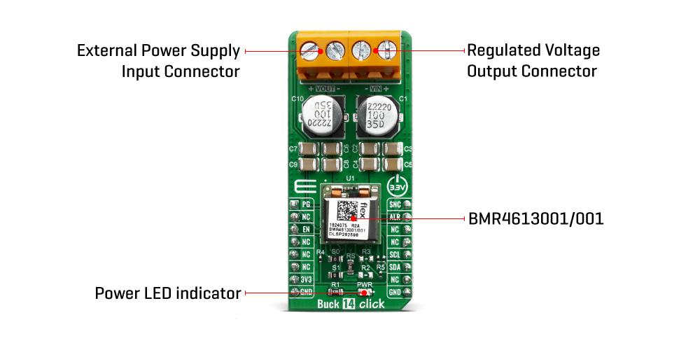
ONBOARD SETTINGS AND INDICATORS
| Label | Name | Default | Description |
|---|---|---|---|
| PWR | LED GREEN | - | Power LED Indicator |
| VIN | - | - | External Power Supply Input Connector |
| VOUT | - | - | Regulated Voltage Output Connector |
BUCK 14 CLICK ELECTRICAL SPECIFICATIONS
| Description | Min | Typ | Max | Unit |
|---|---|---|---|---|
| Output voltage | 0.6 | - | 5 | V |
| Output current | 0 | - | 12 | A |
| Input voltage | 4.35 | - | 14 | V |
SOFTWARE SUPPORT
We provide a library for the Buck 14 Click on our LibStock page, as well as a demo application (example), developed using MikroElektronika compilers. The demo can run on all the main MikroElektronika development boards.
Library Description
Library provides control over device pins, you can read state of some pins. You have ability to send and receive data from device, and control output V.
Key functions:
void buck14_read_data (uint8_t cmd, uint8_t *data_buf, uint8_t n_buf_size )- Reads data from specific registar to buffervoid buck14_write_data (uint8_t cmd, uint8_t *data_buf, uint8_t n_buf_size )- Writes data to specific registar to bufferuint8_t buc14_write_vout( float vout )- Sets output Vuint16_t buc14_read_vout( void )- Returns output V in mV
Examples description
The application is composed of three sections :
- System Initialization - Initialization of SPI module and setting pins to output
- Application Initialization - Configure device, checks id, writes default command VOUT, checks if power is OK
- Application Task - Sends 4 different commands for VOUT in span of 8sec
void application_task ( )
{
vout_value = 1.2;
status_data = buc14_write_vout( vout_value );
error_handler( status_data );
if ( status_data == BUCK14_SUCCESSFUL )
{
read_vout_data(  );
}
Delay_ms( 8000 );
vout_value = 3.7;
status_data = buc14_write_vout( vout_value );
error_handler( status_data );
if ( status_data == BUCK14_SUCCESSFUL )
{
read_vout_data(  );
}
Delay_ms( 8000 );
vout_value = 2.5;
status_data = buc14_write_vout( vout_value );
error_handler( status_data );
if ( status_data == BUCK14_SUCCESSFUL )
{
read_vout_data(  );
}
Delay_ms( 8000 );
vout_value = 4.5;
status_data = buc14_write_vout( vout_value );
error_handler( status_data );
if ( status_data == BUCK14_SUCCESSFUL )
{
read_vout_data(  );
}
Delay_ms( 4000 );
mikrobus_logWrite( "```````````````", _LOG_LINE );
Delay_ms( 4000 );
}
Additional Functions :
- void error_handler ( uint8_t stat_data ) - Check if there was error in stat_data and returns message
- void read_vout_data ( void ) - Reads current VOUT in mV
Note :
- When you send data you should send LSB first
- Device input V should be beetween 4.5 - 14 V
- Device output V could be from 0.5 - 5 V deepending from limits you set currently it is set to 1V
The full application code, and ready to use projects can be found on our LibStock page.
Other mikroE Libraries used in the example:
- Conversions
- I2C
- UART
Additional notes and informations
Depending on the development board you are using, you may need USB UART click, USB UART 2 click or RS232 click to connect to your PC, for development systems with no UART to USB interface available on the board. The terminal available in all MikroElektronika compilers, or any other terminal application of your choice, can be used to read the message.
MIKROSDK
This Click board™ is supported with mikroSDK - MikroElektronika Software Development Kit. To ensure proper operation of mikroSDK compliant Click board™ demo applications, mikroSDK should be downloaded from the LibStock and installed for the compiler you are using.