
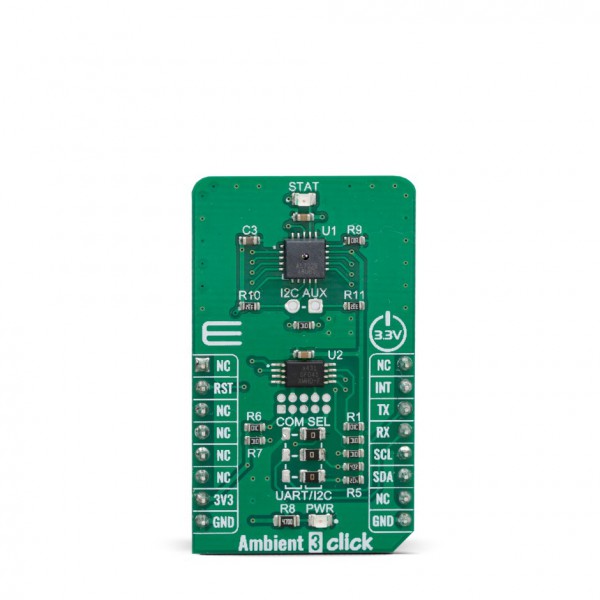
Ambient 3 Click


- Order number: MIKROE-3686
- Manufacturer product ID: 3686
Ambient 3 Click is calibrated XYZ chromatic smart lighting director, providing the measurement data in digital format over the I2C interface. It utilizes the AS7225, a miniature light sensor with UART and I2C interfaces. Packed in a small casing, this sensor can provide calibrated for life nano-optic sensor providing direct CIE1931 XYZ and CIE 1976 u’v’ coordinate mapping. A well-proven, integrated tristimulus sensing element designed to meet the XYZ standard observer response that mimic the human eye and is extremely stable over both operating temperature and time. The device contains a 16-bit integrating analog-to-digital converter, which integrates current from the photodiodes. To ensure the integrity of the data, upon completion of an integration cycle, results are transferred to double-buffered registers.
Ambient 3 click is supported by a mikroSDK compliant library, which includes functions that simplify software development. This Click board™ comes as a fully tested product, ready to be used on a system equipped with the mikroBUS™ socket.
Thanks to the used proprietary technologies that allow high precision, reliability, and low power consumption, Ambient 3 click can be used for a rapid development of various cost-effective applications that rely on light intensity sensing, including CCT chromatic tuning luminaires systems, backlight dimming applications for mobile and handheld devices, light metering applications (lux meters), and similar.
HOW DOES IT WORK?
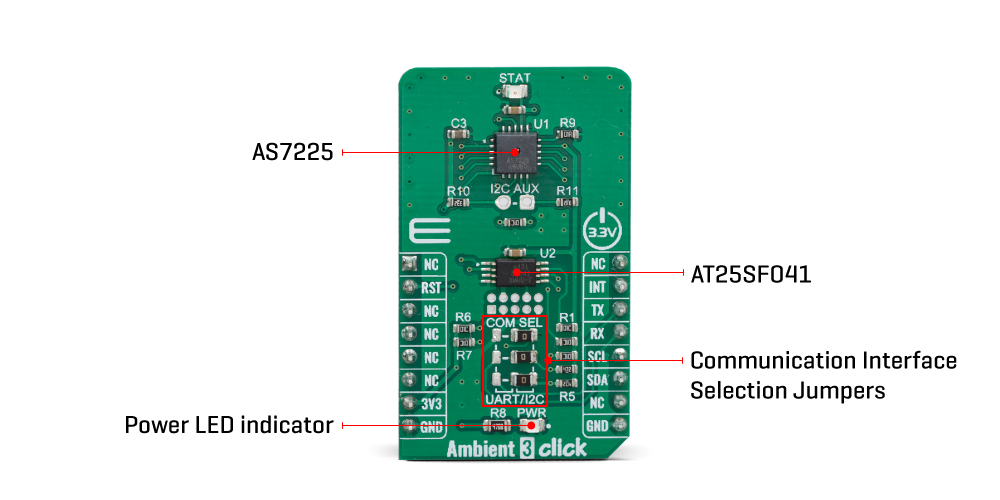
The main component of the Ambient 3 click is the AS7225, a calibrated XYZ chromatic smart lighting director with UART and I2C interfaces, from ams AG. This sensor utilizes Standard observer tristimulus (XYZ) interference filters, which are applied to the Calibrated XYZ Chromatic Smart Lighting Director optical channels as part of the CMOS process. By utilizing a sensitive photo-diode, low noise amplifier, and a 16-bit A/D converter (ADC), this sensor can provide the data directly, with no need for complex calculations. Calibration is accomplished using standard white LEDs at a variety of CCTs to deliver high accuracy and eliminate the need for light-by-light calibration in most designs. A high dynamic range along with a linear response to different light sources, allows this sensor to be placed behind a dark glass or panels made of other semi-transparent materials.
The AS7225 sensors registers are organized into seven main groups, which makes it very simple to configure and use. Even though, it comes with the mikroSDK compatible library, which simplifies the development even more. However, more detailed explanation of each command can be found in the datasheet of the AS7225, if required.
By using these registers, the user can configure the Click board™ and the equipped AS7225 sensor, fine-tuning it according to the requirements of the application. All the working parameters including the sensitivity, integration time, interrupt detection, persistence protection for the interrupt triggering, low and high threshold window for the interrupt, can all be set using these registers. Finally, the Ambient Light Sensing (ALS) result can be found here in calibrated sensor result register group. The user also can access to the raw value data and calibration coefficients by reading the appropriate registers. The data can be read or written in LSB/MSB format, using the 8-bit I2C interface.
Register bits DATA_RDY give information about finished integration and calculation. An interrupt event will be generated, asserting this pin to a LOW logic level when new calculated PWM dimming percent values are available for the external MCU. If the interrupt register bit for either are enabled (RDY_INT = 1, PWM_INT =1) then when either of these activities become active, indicating available data, the INT pin is pulled low in addition to setting the ready register bit(s). The INT Line is released when the appropriate control register (CONV_Control and/or DIR_ Control) is read. The interrupt pin is routed to the mikroBUS™ INT pin.
The AS7225 initial setup and ongoing parameter storage is automatically done by software within the required external serial Flash memory, via SPI bus. Therefore, Ambient 3 click has AT25SF041-XMHD-T IC – a 4MB flash memory module onboard. The AS7225 contains a serial UART interface to connect to a flash memory
The Click board™ is supported by the mikroSDK library, which contains functions for simplified development. The mikroSDK functions are well-documented, but there is still a need, the datasheet of the AS7225 offers listing of all the registers and their specific functions.
The Click board™ is designed to work with 3.3V only. When using it with MCUs that use 5V levels for their communication, a proper level translation circuit should be used.
SPECIFICATIONS
| Type | Optical |
| Applications | It can be used for CCT chromatic tuning luminaires systems, backlight dimming applications for mobile and handheld devices, light metering applications (lux meters), and similar. |
| On-board modules | AS7225, a calibrated XYZ chromatic smart lighting director with UART and I2C interfaces, from ams AG. |
| Key Features | Standard observer tristimulus (XYZ) interference filters, spectral response similar to human eye, low power consumption, compact design ideal for building IoT applications. |
| Interface | I2C,UART |
| Click board size | M (42.9 x 25.4 mm) |
| Input Voltage | 3.3V |
PINOUT DIAGRAM
This table shows how the pinout on Ambient 3 click corresponds to the pinout on the mikroBUS™ socket (the latter shown in the two middle columns).
| Notes | Pin | Pin | Notes | ||||
|---|---|---|---|---|---|---|---|
| NC | 1 | AN | PWM | 16 | NC | ||
| NC | 2 | RST | INT | 15 | INT | Interrupt out | |
| NC | 3 | CS | RX | 14 | TX | UART Transmit | |
| NC | 4 | SCK | TX | 13 | RX | UART Receive | |
| NC | 5 | MISO | SCL | 12 | SCL | I2C Clock | |
| NC | 6 | MOSI | SDA | 11 | SDA | I2C Data | |
| Power Supply | 3.3V | 7 | 3.3V | 5V | 10 | NC | |
| Ground | GND | 8 | GND | GND | 9 | GND | Ground |
ONBOARD SETTINGS AND INDICATORS
| Label | Name | Default | Description |
|---|---|---|---|
| LD1 | PWR | - | Power LED Indicator |
| LD2 | STAT | - | Status indicator |
SOFTWARE SUPPORT
We provide a library for the Ambient 3 click on our LibStock page, as well as a demo application (example), developed using MikroElektronika compilers. The demo can run on all the main MikroElektronika development boards.
Library Description
Library initializes and defines I2C bus driver and driver functions which offer a choice to write data in registers and to read data from registers. Library also offers a choice to reads device temperature and ambient light in LUX. The user also has the function for reset chip and function for read interrupt state.
Key functions:
uint8_t ambient3_readByte(uint8_t virtualReg)- Function for reads one byte.uint8_t ambient3_getDeviceTemperature()- Function for reading device temperature.float ambient3_getDataInLUX()- Function for reads Light data in LUX.
Examples description
The application is composed of three sections :
- System Initialization - Initializes I2C module and sets INT pin as INPUT and RST pin as OUTPUT
- Application Initialization - Driver init and reset chip
- Application Task - (code snippet) - Reads the device temperature, daylight at LUX and logs data to USBUART every 1 sec
void applicationTask()
{
mikrobus_logWrite(" - Device temperature : ", _LOG_TEXT);
Temperature = ambient3_getDeviceTemperature();
IntToStr(Temperature, demoText_Temp);
mikrobus_logWrite(demoText_Temp, _LOG_LINE);
mikrobus_logWrite(" - Light in LUX : ", _LOG_TEXT);
dataLUX = ambient3_getDataInLUX();
FloatToStr(dataLUX, demoText_dataLUX);
mikrobus_logWrite(demoText_dataLUX, _LOG_LINE);
Delay_ms(1000);
}
The full application code, and ready to use projects can be found on our LibStock page.
Other mikroE Libraries used in the example:
- I2C
Additional notes and informations
Depending on the development board you are using, you may need USB UART click, USB UART 2 click or RS232 click to connect to your PC, for development systems with no UART to USB interface available on the board. The terminal available in all MikroElektronika compilers, or any other terminal application of your choice, can be used to read the message.
MIKROSDK
This Click board™ is supported with mikroSDK - MikroElektronika Software Development Kit. To ensure proper operation of mikroSDK compliant Click board™ demo applications, mikroSDK should be downloaded from the LibStock and installed for the compiler you are using.
For more information about mikroSDK, visit the official page.