
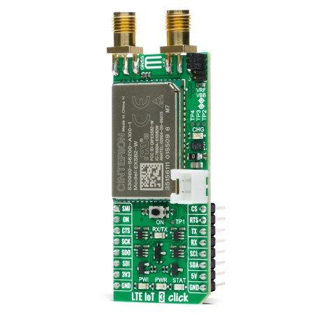
LTE IoT 3 Click


- Order number: MIKROE-4118
- Manufacturer product ID: 4118
LTE IoT 3 Click is a compact add-on board that contains a Low Power Wide Area (LPWA) Wireless IoT module that allows connections to the LTE CAT-M1, CAT NB1/2, and 2G networks. This board features the EXS82-W, LTE-IoT Wireless Module from Thales that offers a rich set of Internet protocols and industry-standard interfaces such as UART, USB, etc. Global IoT connectivity, integrated GNSS support, SMS support, extended coverage range, and reduced power consumption makes this single IoT module an excellent choice for device makers while ensuring worldwide reliability. This Click board™ is fitting for small, battery-operated devices in remote locations such as smart meters, asset trackers, healthcare apps, wearables, smart city solutions, and many more.
LTE IoT 3 Click is supported by a mikroSDK compliant library, which includes functions that simplify software development. This Click board™ comes as a fully tested product, ready to be used on a system equipped with the mikroBUS™ socket.
LTE IoT 3 Click is based on the EXS82-W, a Low Power Wide Area (LPWA) Wireless IoT module that allows connections to the LTE CAT-M1, CAT NB1/2, and 2G networks from Thales. EXS82 IoT module supports all LTE bands and offers an efficient architecture with PSM and eDRX plus embedded processing. The EXS82 also includes a module services engine that supports a range of Internet services and optimized operations. State of the art security features protect the device as well as data and provide secure enrollment in cloud platforms enabling trust in the IoT ecosystem. The module’s simplified power supply design and advanced management system extend battery lifetime and improve the total cost of ownership.
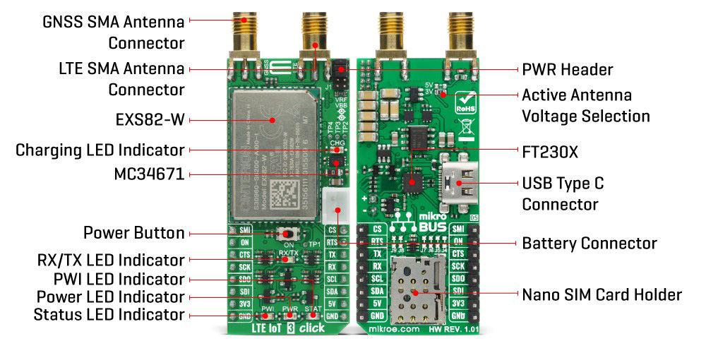
The integrated GNSS receiver supports the NMEA protocol via the ASC0 interface, which represents combined electrical and data specification for communication between various electronic devices including GNSS receivers. By default, the GNSS receiver is switched off. It has to be switched on and configured using AT commands.
This Click board™ is equipped with the USB type C connector. It allows the module to be powered and configured by a personal computer (PC) using FT230X, a compact USB to a basic serial UART interface device which has been designed to operate efficiently with USB host controllers by using as little bandwidth as possible when compared to the total USB bandwidth available. The UART interface operates at 115200 bps and it is used for exchanging AT commands with the host, data transfer, and the firmware update. It also possesses the RX/TX LED Indicator whose indicates whether the bridge is in RX or TX function.
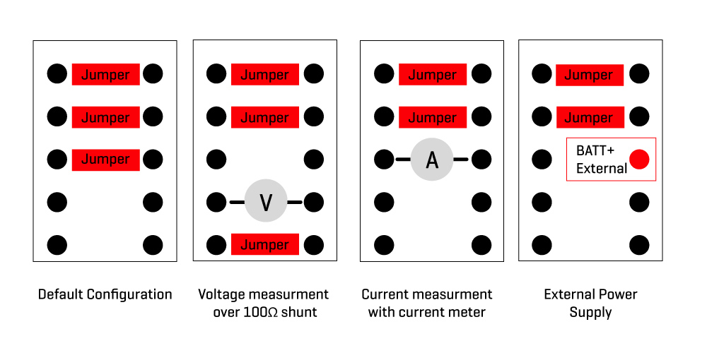
PWR Header can be used for power consumption monitoring:
LTE IoT 3 Click can be battery powered and used as a stand-alone device. It also has MC34671, a fully-integrated Li-Ion or Li-Polymer battery charger that allows charging of battery when Click board™ is inserted in mikroBUS™ socket or plugged into a USB port, while the CHG LED indicator which will indicate the charging in progress and will turn off once the battery charging is finished. The Nano SIM card holder on the back of the Click board™ is used to install a nano-SIM card. Two SMA antenna connectors with an impedance of 50Ω are used for connecting the appropriate antennas: there is one SMA connector for LTE antenna and the second one for GNSS antenna on which active antennas can be used either supplied with 3V or 5V, that can be selected by appropriate jumper (J2 or J3).
The yellow LED labeled as STAT is used to visually indicate different operating modes of the module. Another indicator that this Click board™ has is the PWI LED indicator that reports the module’s power state and shows whether it is active or in Power-Down mode. The onboard pushbutton labeled as ON is routed to the RST pin on the mikroBUS™ and it represents the ignition button.
This Click Board™ uses the UART communication interface, but it is also left the option for the user to use other interfaces such as SPI and I2C if he wants to configure the module as SPI or I2C Master and write the library by himself. That can be achieved by populating the appropriate jumpers on the back of the board (J4 – J9), depending on the desired communication.
This Click board™ can be interfaced with both 3.3V and 5V MCUs because a proper logic voltage level conversion is performed by appropriate voltage level shifters, while the on-board LDOs are ensuring that the module is powered by recommended voltage levels.
Specifications:
| Type | GPS+GNSS,LTE IoT |
| Applications | Can be used for small, battery-operated devices in remote locations such as smart meters, asset trackers, healthcare apps, wearables, smart city solutions, and many more. |
| On-board modules | LTE IoT 3 Click is based on the EXS82-W, a Low Power Wide Area (LPWA) Wireless IoT module that allows connections to the LTE CAT-M1, CAT NB1/2, and 2G networks from Thales. |
| Key Features | Power saving modes, LTE bands that allows multiple regions coverage, dual SMA antenna connectors, USB connectivity, visual network and status indication, and more |
| Interface | UART,USB |
| Compatibility | mikroBUS |
| Click board size | L (57.15 x 25.4 mm) |
| Input Voltage | 3.3V,5V |
PinOut Diagram:
This table shows how the pinout on LTE IoT 3 Click corresponds to the pinout on the mikroBUS™ socket (the latter shown in the two middle columns).
| Notes | Pin |
| Pin | Notes | |||
|---|---|---|---|---|---|---|---|
| SUSPEND Mode | SMI | 1 | AN | PWM | 16 | CS | SPI Chip Select |
| Ignition | ON | 2 | RST | INT | 15 | RTS | Ready to Send |
| Clear to Send | CTS | 3 | CS | RX | 14 | TX | UART TX |
| SPI Clock | SCK | 4 | SCK | TX | 13 | RX | UART RX |
| SPI Data OUT | SDO | 5 | MISO | SCL | 12 | SCL | I2C Clock |
| SPI Data IN | SDI | 6 | MOSI | SDA | 11 | SDA | I2C Data |
| Power Supply | 3.3V | 7 | 3.3V | 5V | 10 | 5V | Power Supply |
| Ground | GND | 8 | GND | GND | 9 | GND | Ground |
OnBoard Settings And Indicators:
| Label | Name | Default | Description |
|---|---|---|---|
| LD1 | PWR | - | Power LED Indicator |
| LD2 | CHG | - | Charging LED Indicator |
| LD3 | PWI | - | PWI LED Indicator |
| LD4 | STAT | - | Status LED Indicator |
| LD5 | RX/TX | - | RX/TX LED Indicator |
| SW1 | ON | - | Power button: Power ON - hold pressed for 150ms, Power OFF - hold pressed for 1.5s |
| J1 | - | Populated 1.2.3 | Power Consumption Monitoring |
| J2,J3 | - | J2 populated, | Active GNSS antenna power selection |
| J4 - J7 | - | not populated | SPI selection |
| J8, J9 | - | not populated | I2C selection |
| CN1 | GNSS | - | GNSS SMA Antenna Connector |
| CN2 | LTE | - | LTE SMA Antenna Connector |
| SIM | SIM | - | Nano SIM Card Holder |
LTE IOT 3 Click Electrical Specifications:
| Description | Min | Typ | Max | Unit |
|---|---|---|---|---|
| Supply Voltage | 2.6 | - | 4.8 | V |
| GSM QUAD-Band Range | 850 | - | 1900 | mHz |
| LTE NBIOT 17-Band Range | 600 | - | 2100 | mHz |
| LTE Cat-M 17-Band Range | 700 | - | 2100 | mHz |
| Operating Temperature Range | -40 | - | +90 | °C |
Software Support:
We provide a library for the LTE IoT 3 Click on our LibStock page, as well as a demo application (example), developed using MikroElektronika compilers. The demo can run on all the main MikroElektronika development boards.
Library Description
Library provides function for controlling device pins, and function for sendint AT commands over UART communication.
Key functions:
-
void lteiot3_send_cmd ( uint8_t *cmd_buf )- Function for sending commands to device. -
void lteiot3_set_pin_on ( uint8_t pin_state- Function for setting on pin state.
Examples description
The application is composed of three sections :
-
System Initialization - Initialization of UART MODULE and additional pins
-
Application Initialization - Turns on device and sends initial commands
-
Application Task - Checks some device parameters by sending AT commands
void application_task ( )
{
lteiot3_send_cmd( &AT_CGATT[0] );
Delay_ms( 5000 );
log_buffer();
lteiot3_send_cmd( &AT_CEREG[0] );
Delay_ms( 5000 );
log_buffer();
lteiot3_send_cmd( &AT_CSQ[0] );
Delay_ms( 5000 );
log_buffer();
}
The full application code, and ready to use projects can be found on our LibStock page.
Other mikroE Libraries used in the example:
-
Conversions
-
UART
Additional notes and informations
Depending on the development board you are using, you may need USB UART click, USB UART 2 click or RS232 click to connect to your PC, for development systems with no UART to USB interface available on the board. The terminal available in all MikroElektronika compilers, or any other terminal application of your choice, can be used to read the message.
MikroSDK:
This Click board™ is supported with mikroSDK - MikroElektronika Software Development Kit. To ensure proper operation of mikroSDK compliant Click board™ demo applications, mikroSDK should be downloaded from the LibStock and installed for the compiler you are using.
For more information about mikroSDK, visit the official page.
Resources:
Downloads:
LTE IoT 3 click example on Libstock