
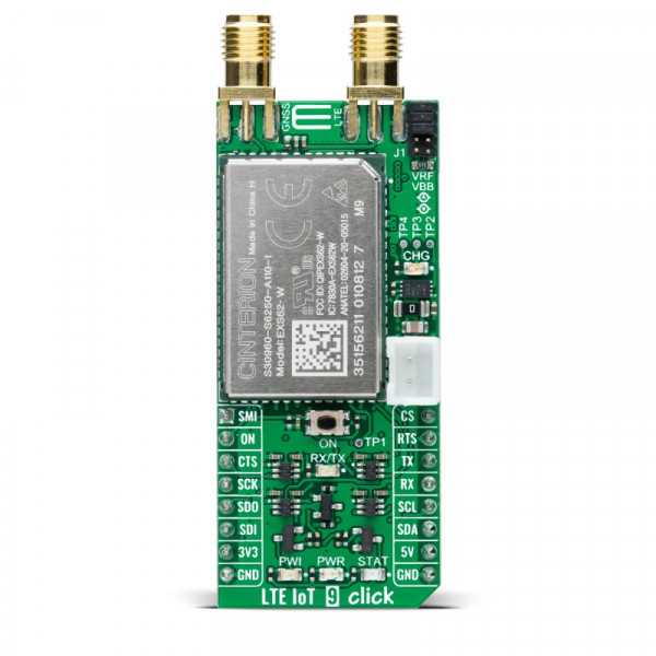
LTE IoT 9 Click


- Order number: MIKROE-4465
- Manufacturer product ID: 4465
LTE IoT 9 Click is a compact add-on board that contains a Low Power Wide Area (LPWA) Wireless IoT module which is 3GPP Release 14 compliant. It allows connections to the LTE CAT-M1 and CAT NB1/2 network. This board features the EXS62-W, LTE-IoT Wireless Module from Thales that offers a rich set of Internet protocols and industry-standard interfaces such as UART, USB, etc. Global IoT connectivity, integrated GNSS support, SMS support, extended coverage range, and reduced power consumption make this single IoT module an excellent choice for device makers while ensuring worldwide reliability. This Click board™ is suitable for applications such as logistics and asset tracking, predictive maintenance, industrial, smart agriculture, and many more.
LTE IoT 9 Click is supported by a mikroSDK compliant library, which includes functions that simplify software development. This Click board™ comes as a fully tested product, ready to be used on a system equipped with the mikroBUS™ socket.
How Does It Work?
LTE IoT 9 Click as its foundation uses the EXS62-W, a cellular IoT Module from Thales that supports 3GPP Release 14, global machine type communication (MTC) technologies, NB-IoT, LTE M, and 5G-enabled LPWA connectivity for industrial applications. It provides integrated GNSS support and delivers up to 20dBm of power, providing a downlink data speed of up to 300Kbps and an uplink data speed of up to 1.1Mbps. State-of-the-art security features protect the device and data and provide secure enrollment in cloud platforms enabling trust in the IoT ecosystem. The module’s simplified power supply design and advanced management system extend battery lifetime.
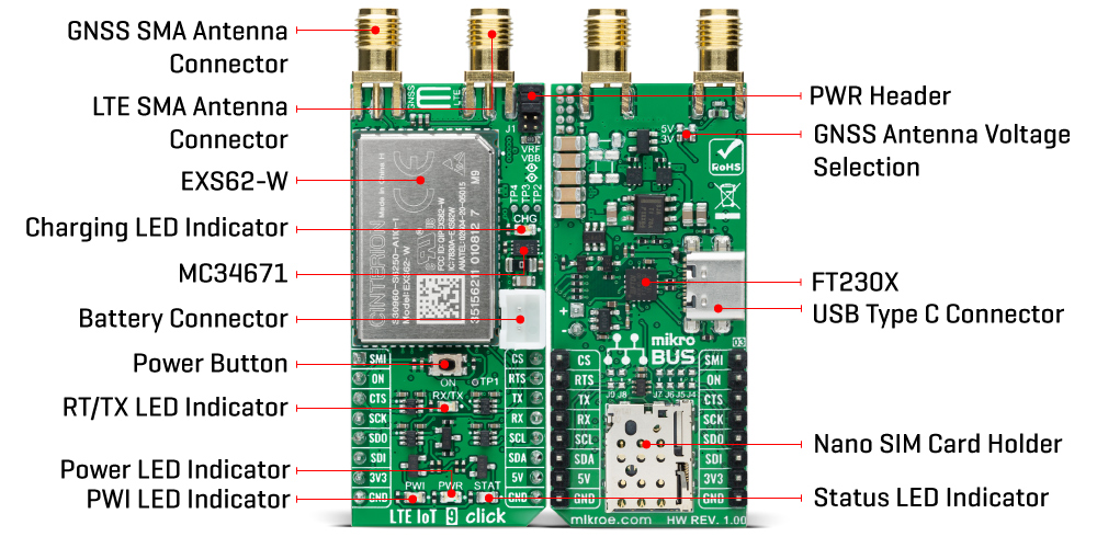
This Click board™ is equipped with a USB type C connector. It allows the module to be powered and configured by a personal computer (PC) using FT230X, a compact USB to a serial UART interface device designed to operate efficiently with USB host controllers. It uses as little bandwidth as possible when compared to the total USB bandwidth available.
Also, it possesses two SMA antenna connectors with an impedance of 50Ω, labeled as GNSS and LTE, used for connecting the appropriate antenna that Mikroe has in its offer. The integrated GNSS receiver supports the NMEA protocol, representing combined electrical and data specifications for communication between various electronic devices, including GNSS receivers. By default, the GNSS receiver is OFF, and if the user wants to activate it, switching to the ON state can be done via AT commands. GNSS antenna also offers supply selection of 3V or 5V selected by appropriate jumper J2 or J3. Besides those SMA connectors, this Click board™ also has a nano-SIM card slot that provides multiple connections and interface options.
LTE IoT 9 Click communicates with MCU using the UART interface as its default communication protocol for exchanging AT commands with the host, data transfer, and firmware update. It also possesses the RX/TX LED indicator that indicates whether the bridge is in RX or TX function. The users can also use other interfaces such as SPI or I2C to configure the module and write the library by themselves by populating the appropriate jumpers on the Click board's bottom (J4 – J9).
This Click board™ can be battery-powered and used as a stand-alone device. It also contains the MC34671, a fully-integrated Li-Ion or Li-Polymer battery charger allowing a battery charge when Click board™ is inserted in mikroBUS™ socket or plugged into a USB port with the CHG LED indicator used as an indicator of the charging progress. CHG LED will turn off once the battery charging is finished.
Another indicator that this Click board™ has, in addition to the yellow LED labeled as STAT that indicates different operating modes of the module, is the blue LED labeled as PWI that reports the module’s power state and shows whether it is active or in Power-Down mode. The onboard pushbutton labeled as ON is routed to the RST pin on the mikroBUS™ representing the Ignition button.
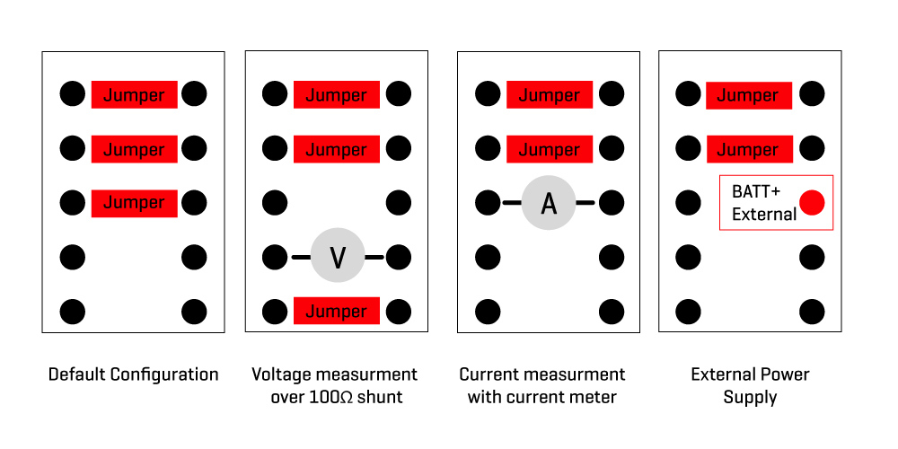
An additional feature of this Click board™ is a PWR Header used for power consumption monitoring:
 This Click board™ can operate with both 3.3V and 5V MCUs. A proper logic voltage level conversion is performed by appropriate voltage level shifters, while the on-board LDOs ensure that the recommended voltage levels power module. However, the Click board™ comes equipped with a library containing easy-to-use functions and an example code that can be used, as a reference, for further development.
Specifications:
| Type | GPS+GNSS,LTE IoT |
| Applications | Can be used for applications such as logistics and asset tracking, predictive maintenance, industrial, smart agriculture, and many more. |
| On-board modules | EXS62-W - a cellular IoT Module from Thales that supports 3GPP Release 14 and all LTE bands. |
| Key Features | Power saving modes, LTE bands that allows multiple regions coverage, dual SMA antenna connectors, USB connectivity, visual network and status indication, and more. |
| Interface | I2C,SPI,UART,USB |
| Click board size | L (57.15 x 25.4 mm) |
| Input Voltage | 3.3V or 5V |
Pinout Diagram:
This table shows how the pinout on LTE IoT 9 Click corresponds to the pinout on the mikroBUS™ socket (the latter shown in the two middle columns).
| Notes | Pin | Pin | Notes | ||||
|---|---|---|---|---|---|---|---|
| SUSPEND Mode | SMI | 1 | AN | PWM | 16 | CS | SPI Chip Select |
| Ignition | ON | 2 | RST | INT | 15 | RTS | UART Ready to Send |
| UART Clear to Send | CTS | 3 | CS | RX | 14 | RX | UART RX |
| SPI Clock | SCK | 4 | SCK | TX | 13 | TX | UART TX |
| SPI Data OUT | SDO | 5 | MISO | SCL | 12 | SCL | I2C Clock |
| SPI Data IN | SDI | 6 | MOSI | SDA | 11 | SDA | I2C Data |
| Power Supply | 3.3V | 7 | 3.3V | 5V | 10 | 5V | Power Supply |
| Ground | GND | 8 | GND | GND | 9 | GND | Ground |
OnBoard Settings And Indicators:
| Label | Name | Default | Description |
|---|---|---|---|
| LD1 | PWR | - | Power LED Indicator |
| LD2 | CHG | - | Charging LED Indicator |
| LD3 | PWI | - | PWI LED Indicator |
| LD4 | STAT | - | Status LED Indicator |
| LD5 | RX/TX | - | RX/TX LED Indicator |
| SW1 | ON | - | Power button: Power ON - hold pressed for 150ms, Power OFF - hold pressed for 1.5s |
| J1 | - | Populated 1.2.3 (Default) | Power Consumption Monitoring Header |
| J2-J3 | - | J2 Populated | GNSS Antenna Voltage Selection |
| J4-J7 | - | Unpopulated | SPI Interface Selection |
| J8-J9 | - | Unpopulated | I2C Interface Selection |
LTE IOT 9 Click Electrical Specifications:
| Description | Min | Typ | Max | Unit |
|---|---|---|---|---|
| Supply Voltage | 3.3 | - | 5 | V |
| Operating Frequency Range | 850 | - | 1800 | MHz |
| Operating Temperature Range | -40 | +25 | +90 | °C |
Software Support:
We provide a library for the LTE IoT 9 Click as well as a demo application (example), developed using MikroElektronika compilers. The demo can run on all the main MikroElektronika development boards.
Package can be downloaded/installed directly from NECTO Studio Package Manager(recommended way), downloaded from our LibStock™ or found on mikroE github account.
Library Description:
This library contains API for LTE IoT 9 Click driver.
Key functions:
lteiot9_cfg_setup- Config Object Initialization function.lteiot9_init- Initialization function.lteiot9_default_cfg- Click Default Configuration function.
Examples description:
This application shows capability of LTE IoT 9 Click board™. It connects to network with standard "AT" commands, then sends SMS whit SIM card, and then logs GNNS data.
The demo application is composed of two sections :
void application_task ( void )
{
switch( app_connection_status )
{
case CONFIGURATION_FOR_NETWORK:
{
lteiot9_config_device_for_network( );
break;
}
case CHECK_NETWORK_CONNECTION:
{
lteiot9_check_connection_to_network( );
break;
}
case SENDING_SMS:
{
lteiot9_send_sms( );
break;
}
case CONFIGURATION_FOR_GNSS:
{
lteiot9_config_device_for_gnss( );
break;
}
case GNSS_DATA:
{
lteiot9_gnss_data();
break;
}
default:
{
log_error( &logger, "Application status error!" );
app_connection_status = CHECK_NETWORK_CONNECTION;
Delay_ms( 1000 );
break;
}
}
}
The full application code, and ready to use projects can be installed directly from NECTO Studio Package Manager(recommended way), downloaded from our LibStock™ or found on mikroE github account.
Other mikroE Libraries used in the example:
- MikroSDK.Board
- MikroSDK.Log
- Click.LTEIoT9
Additional notes and informations:
Depending on the development board you are using, you may need USB UART click, USB UART 2 click or RS232 click to connect to your PC, for development systems with no UART to USB interface available on the board. The terminal available in all MikroElektronika compilers, or any other terminal application of your choice, can be used to read the message.
MikroSDK
This Click board™ is supported with mikroSDK - MikroElektronika Software Development Kit. To ensure proper operation of mikroSDK compliant Click board™ demo applications, mikroSDK should be downloaded from the LibStock and installed for the compiler you are using.
For more information about mikroSDK, visit the official page.
Resources:
Downloads:
LTE IoT 9 click example on Libstock