
Brushless 4 click


- Order number: MIKROE-3019
- Manufacturer product ID: 3019
Brushless 4 click is a 3 phase sensorless BLDC motor driver, which features a 180° sinusoidal drive, providing high efficiency and low acoustic noise. This type of drivers inherently provides higher torque in general, compared to classical 120° BLDC motor drivers. Brushless 4 click allows a wide voltage range to be used for the power supply: from 2V, up to 14V. The Click board™ features a standard set of protection features: overvoltage protection, overtemperature protection, overcurrent limiting, but also some more specific protection features, such as the rotor lock-up protection and automatic restart function.
Brushless 4 click is a 3 phase sensorless BLDC motor driver, which features a 180° sinusoidal drive, providing high efficiency and low acoustic noise. This type of drivers inherently provides higher torque in general, compared to classical 120° BLDC motor drivers. Brushless 4 click allows a wide voltage range to be used for the power supply: from 2V, up to 14V. The Click board™ features a standard set of protection features: overvoltage protection, overtemperature protection, overcurrent limiting, but also some more specific protection features, such as the rotor lock-up protection and automatic restart function.
The Click board™ itself has a low count of external components, considering all the features it has to offer. The power transistors are integrated into the driver IC, it requires no tuning, and no sensor is used, making the circuit very simple and cost-effective. With all the features it has, it is a perfect solution for building a reliable low-cost motor driver applications, such as the low noise computer cooling fans, efficient air ventilation systems, and similar applications that could benefit of having reliable and reasonably simple motor driver circuit.
HOW DOES IT WORK?
The main component of the Brushless 4 click is the MCP8063, a 3 phase brushless sinusoidal sensorless motor driver, from Microchip. This IC has many features that make it a perfect choice for driving a wide range of small to medium BLDC motors. The MCP8063 requires a very low count of external components, due to its high degree of integration. It provides the rotor position digital output, via the FG pin, routed to the mikroBUS™ INT pin, which is also labeled as FG on the Click board™ itself. The rotation speed control is implemented via the PWM pin of the mikroBUS™, routed to the PWM input pin of the IC. One of the most distinctive features of the Brushless 4 click is the 180° sinusoidal drive, which provides more torque and better efficiency than the more commonly used 120° driver topology.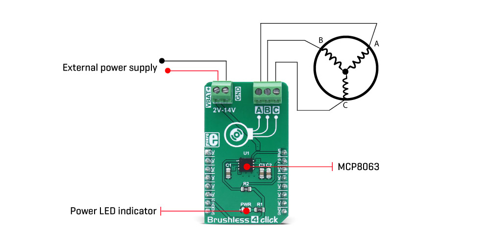
As mentioned above, the PWM signal can be used to control the motor speed. The duty cycle controls the speed of the rotor, while the frequency of the PWM signal doesn’t affect the rotation speed and can vary between 20 Hz and 100 kHz. When the PWM input is at the HIGH logic level, the rotational speed of the motor will be at a maximum. When the PWM input stays at the LOW logic level, the motor is stopped. Toggling between HIGH and LOW logic state will result in the rotor turning at a specific speed, which depends on the duration of the HIGH logic level state. The PWM pin is routed to the same named pin of the mikroBUS™, conveniently allowing the MCU to provide the required PWM signal.
Another method of controlling the motor speed can be implemented by varying the voltage of the motor power supply, which is connected via the input screw terminal, labeled as VBAT. This voltage can range from 2V, up to 14V. The power supply has to be connected to the input terminal, as this terminal provides power for both the output stage of the MCP8063, as well as for the internal logic circuit (through the internal voltage regulator).
The rotational speed and phase of the motor can be determined by using the FG pin. This pin acts like the Hall-effect sensor output, providing information about the speed and the phase of the motor to the host MCU, via the mikroBUS™. The FC pin is pulled up with the onboard resistor. When the lock-up or desync condition appears, this pin is set to a high impedance mode, meaning it is pulled to a HIGH logic level - because of the pull-up resistor. To calculate the RPM (rounds per minute) the formula below should be used. Please note that the result depends on the type of the used motor since the number of its slots and poles are part of the calculation:

P = Total number of poles in the motor
S = Total number of slots in the motor
When the rotor is blocked or it loses synchronization, an internal lock-up section detects this condition and ties the coils to GND, effectively discharging the rotor with minimal self-heating. After a time-out, another attempt is made to run the rotor. If it is still blocked, another lock-up event is detected and another time-out period is initiated. This way, the rotor is protected from overheating.
As already mentioned, the MCP8063 IC features a current limit protection. The maximum current is internally limited to 1.5A. This limitation prevents overheating of the motor coils, as well as protecting the output stage transistors. A good practice is to always keep the power consumption lower than the maximum specified, ensuring there is enough overhead. The thermal protection protects the IC when it reaches 170°C, with a hysteresis of 25°C before the restart is attempted, meaning that the IC has to be cooled down to 145°C.
The output 3 pole screw terminal is used to connect the motor phases. It is labeled with A, B, and C, allowing connecting of the 3 pole BLDC motors which do not require more than 1.5A (when the internal overcurrent limit is triggered).
Brushless 4 click supports only 3.3V MCUs and it is not intended to be connected or controlled via the 5V MCU without a proper level shifting circuitry.
180° VS 120°
In the 120° driver configuration, only two transistors are in the conductive state at a time, energizing only two windings of the BLDC. This means that one winding will not be used at all, not contributing to the torque at all. In the 180° driver configurations, all the phases are energized and three transistors are conductive at a time. This provides better torque and efficiency, as no phases are left unpowered and all three phases contribute to the rotor torque at the same time. This can be illustrated with the simplified schematic below, where the output stage transistors are replaced with the switches. The current through the coils is illustrated by the dots (outwards direction) and crosses (inwards direction).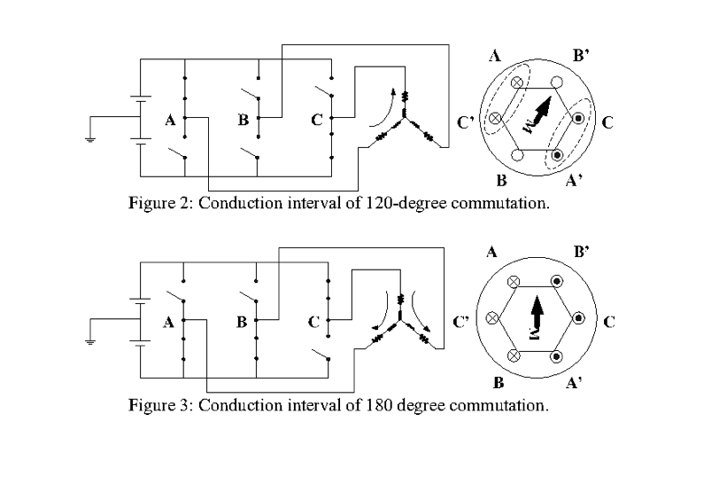
SPECIFICATIONS
| Type | Brushless |
| Applications | General purpose small to medium 2V to 14V sensorless BLDC motor driving, silent computer cooling fan driving, efficient air ventilation systems, and similar applications that could benefit of having reliable and simple motor driver circuit. |
| On-board modules | MCP8063, a 3 phase brushless sinusoidal sensorless motor driver, from Microchip. |
| Key Features | Overvoltage protection, overtemperature protection, overcurrent limiting, rotor lock-up protection, automatic restart function, sensorless operation, low count of additional components required, edge terminals for an easy connection. |
| Interface | GPIO |
| Compatibility | mikroBUS |
| Click board size | M (42.9 x 25.4 mm) |
| Input Voltage | 3.3V |
PINOUT DIAGRAM
This table shows how the pinout on Brushless 4 click corresponds to the pinout on the mikroBUS™ socket (the latter shown in the two middle columns).
| Notes | Pin | Pin | Notes | ||||
|---|---|---|---|---|---|---|---|
| NC | 1 | AN | PWM | 16 | PWM | PWM speed control IN | |
| NC | 2 | RST | INT | 15 | FG | Motor speed indication OUT | |
| NC | 3 | CS | RX | 14 | NC | ||
| NC | 4 | SCK | TX | 13 | NC | ||
| NC | 5 | MISO | SCL | 12 | NC | ||
| NC | 6 | MOSI | SDA | 11 | NC | ||
| Power supply | 3.3V | 7 | 3.3V | 5V | 10 | NC | |
| Ground | GND | 8 | GND | GND | 9 | GND | Ground |
BRUSHLESS 4 CLICK ELECTRICAL SPECIFICATIONS
| Description | Min | Typ | Max | Unit |
|---|---|---|---|---|
| OUT1/2/3 maximum current limitation | 1.4 | 1.5 | 1.6 | A |
| Input power supply voltage | 2 | - | 14 | V |
| Lock protection waiting time | 4.0 | 4.5 | 5.0 | s |
| Absolute PWM signal ratings | -0.7 | - | 4 | V |
ONBOARD SETTINGS AND INDICATORS
| Label | Name | Default | Description |
|---|---|---|---|
| LD1 | PWR | - | Power LED indicator |
| TB1 | VBAT | - | External power supply input terminal |
| TB2 | A,B,C | - | BLDC motor connector |
SOFTWARE SUPPORT
We provide a demo application for Brushless 4 click on our Libstock page, as well as a demo application (example), developed using MikroElektronika compilers. The demo can run on all the main MikroElektronika development boards.
Library Description
The library provides generic functions for working with the Click board.
Key functions:
void brushless4_motorParameters(uint8_t poles, uint8_t slots)- Sets the number of poles and slots of the motor. This needs to be set correctly for the calculation to be correctuint16_t brushless4_getSpeed(uint16_t pulseSample)- Calculates the speed of accumulated pulses from the interrupt pin and returns the motor speed value.uint8_t brushless4_intGet()- Returns the state of the interrupt pin.
Example description
The application is composed of three sections:
- System Initialization - Initializes the GPIO structure.
- Application Initialization - Initializes the GPIO driver and configures the PWM
peripheral for controlling the speed of the motor. - Application Task - (code snippet) - Increases and decreases the speed of the motor
demonstrating the speed control.
void applicationTask()
{
for(i=0;i1;i--)
{
brushless4_setSpeed(i);
Delay_ms(10);
}
Delay_ms(1000);
}
void brushless4_pwmInit()- Initializations of the PWM on the mikroBUS 1.void brushless4_setSpeed(uint16_t speed)- Sets the PWM signal for the motor.
The full application code, and ready to use projects can be found on our Libstock page.
Other MikroElektronika libraries used in the example:
- PWM Library
Additional notes and information
Depending on the development board you are using, you may need USB UART click, USB UART 2 click or RS232 click to connect to your PC, for development systems with no UART to USB interface available on the board. The terminal available in all MikroElektronika compilers, or any other terminal application of your choice, can be used to read the message.