
4D-display click


- Order number: MIKROE-3044
- Manufacturer product ID: MIKROE-3044
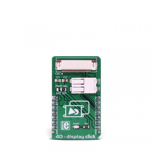
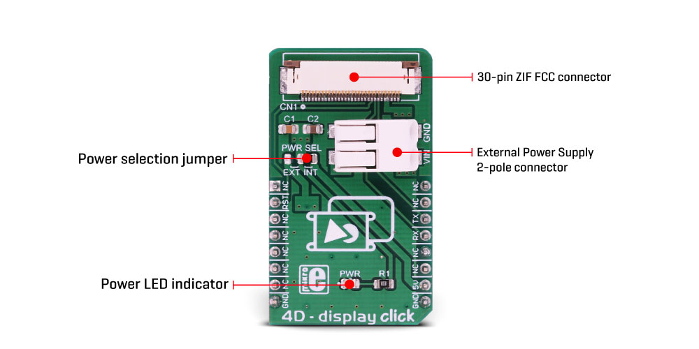
TFT 4D - display click offers a high quality 30-pin ZIF FFC connector for display connection, as well as a 2-pole SMD terminal block for connecting an external power supply, for cases when the connected display demands more power than the mikroBUS™ is able to provide. A small SMD jumper is used to select the external power supply source in this case. This Click board™ offers a reliable and fast UART connection between the 4D intelligent display and the development system, allowing any system equipped with the mikroBUS™ to harness the graphical power of the 4D intelligent display.
How does it work?
4D - display click is an adapter Click board™, used to interface gen4 intelligent display modules produced by 4D Systems, with the MCU systems equipped with the mikroBUS™ socket. The Click board™ is equipped with a high quality 30-pin ZIF FFC connector, which allows reliable and secure connection with the intelligent display module. The gen4 intelligent display modules are equipped with the powerful DIABLO 16 graphic processors from 4D Labs, which are used to accelerate graphic processing. The gen4 display module product family offers ZIF FFC connection interface, so these displays can be used with 4D - display click. By utilizing the proprietary software IDE called 4D Workshop4, it is possible to build accelerated graphic objects on these displays, each with its unique ID, type and value. This information can be exchanged with the smart display module over the UART. This is where 4D - display click adapter comes in handy: by connecting the previously programmed intelligent display module to this Click board™, an interaction between the MCU running a custom firmware and the display itself is made possible.
For example, it is possible to read the ambient light data provided by the UV 4 click installed in the mikroBUS™ socket 2, while showing it on a gauge displayed at the screen of the intelligent display module, connected to the 4D - display click on the mikroBUS™ socket 1. By transmitting the UART data that contains the unique ID of the gauge object and the light intensity reading in the place of the value parameter, the intelligent display will automatically move the gauge scale to show the new updated value. The communication in other direction is possible, too: touching a pre-programmed button can perform an action on the host MCU, which will receive the UART message from the smart display, containing the unique ID of the button object and its pressed state.
Besides the UART RX and TX lines, the RST pin is also routed to the ZIF FFC connector. This pin allows the host controller to reset the display if necessary. The Click board™ also contains a 2-pole SMD terminal block, which is used to connect an external power supply, if required by some of the more power-demanding displays. In this case, the small SMD jumper labeled as the PWR SEL should be moved to the EXT position. This will redirect the display module to use the externally connected power supply. The SMD terminal block allows AWG wire sizes between 18 to 24 to be used. It is very simple to use and establishes reliable connection
More information about 4D intelligent display modules and the software IDE used to program them, can be found on the official site of the 4D Systems.
Specifications
| Type | Adapter |
| Applications | This Click board™ adapter is used to interface the 4D Systems intelligent display equipped with the ZIF FFC, with the MCU system equipped with the mikroBUS™ connector. Allows using the graphical objects on the smart display |
| Key Features | A high quality ZIF FFC and external voltage connector allows powering up more demanding displays with the external PSU. Offers easy connection of the 4D Systems intelligent display with the mikroBUS™ equipped system |
| Interface | UART |
| Input Voltage | 5V |
| Click board size | M (42.9 x 25.4 mm) |
Pinout diagram
This table shows how the pinout on 4D - display click corresponds to the pinout on the mikroBUS™ socket (the latter shown in the two middle columns).
| Notes | Pin | Pin | Notes | ||||
|---|---|---|---|---|---|---|---|
| NC | 1 | AN | PWM | 16 | NC | ||
| Reset | RST | 2 | RST | INT | 15 | NC | |
| NC | 3 | CS | RX | 14 | TX | UART TX | |
| NC | 4 | SCK | TX | 13 | RX | UART RX | |
| NC | 5 | MISO | SCL | 12 | NC | ||
| NC | 6 | MOSI | SDA | 11 | NC | ||
| NC | 7 | 3.3V | 5V | 10 | 5V | Power supply | |
| Ground | GND | 8 | GND | GND | 9 | GND | Ground |
Onboard settings and indicators
| Label | Name | Default | Description | |
|---|---|---|---|---|
| PWR | PWR | - | Power LED indicator | |
| PWR SEL | PWR SEL | Right | Power supply source selection: left position external power supply, right position 5V mikroBUS™ power rail | |
Onboard connectors
| Label | Name | Description |
|---|---|---|
| TB 1 | VIN, GND | External power supply input terminal |
| CN 1 | CN 1 | ZIF FFC for smart display connection |
Software support
We provide a demo application for 4D - display click on our Libstock page, as well as a demo application (example), developed using MikroElektronika compilers. The demo can run on all the main MikroElektronika development boards.
Library Description
Library performs the control of the 4D Systems LCD displays via UART interface by sending the determined commands. The commands can read the objects and write the desired value to the objects, also they support sending the report from the device to the host. Before we start to use this library, first we must perform the LCD display programming. The UART baud rate on LCD and UART baud rate on the host device must be the same. The user can use our demo application for the 4D Systems LCD display, which simulates the speed measurement. For more details check the documentation.
Key functions
void c4d_writeObj( T_C4D_OBJ_P obj )- Function writes the desired value to the desired object.void c4d_readObj( T_C4D_OBJ_P obj )- Function reads the value of the desired object.uint8_t c4d_sendCommand( uint8_t _command, uint8_t *dataIn, uint8_t nBytes )- Function sends command to the display.
Example description
The application is composed of three sections:
- System Initialization - Initializes peripherals and pins.
- Application Initialization - Initializes UART driver, configures timer and puts all objects on the display to the inactive state (initializes display). Also waits about 5 seconds to stabilize the display.
- Application Task - (code snippet) - Performs the display control. The application represents speed measurement. First checks isstart button enabled, and when is it true, reads the value of the slider object and represents that value to the other objects. The slider value is controled by the timer. The user should put Start switch to active state (start application) when Ready LED becomes green. Note: Before you start using this code, first you must perform the display programming by using workshop application. The display programming will define all objects and show your desired objects on the display. Also the microSD card is necessary when you start the display programming, and must be formated as FAT16. When programming is finished puts the microSD card on the display device and then you can start to use this example,
to control all objects on the display.
void applicationTask()
{
c4d_readObj( (T_C4D_OBJ_P)&dipswitch0 );
if (dipswitch0.objValue != _C4D_INACTIVE_STATE)
{
if (enCheck == _C4D_INACTIVE_STATE)
{
led0.objValue = _C4D_ACTIVE_STATE;
c4d_writeObj( (T_C4D_OBJ_P)&led0 );
enCheck = _C4D_ACTIVE_STATE;
TIM2_CR1.CEN = _C4D_ACTIVE_STATE;
}
if (slider0.objValue != prevState)
{
leddigits0.objValue = slider0.objValue * 10;
coolgauge0.objValue = slider0.objValue;
if (slider0.objValue != _C4D_INACTIVE_STATE)
{
userled2.objValue = _C4D_ACTIVE_STATE;
}
else
{
userled2.objValue = _C4D_INACTIVE_STATE;
}
if (slider0.objValue >= 100)
{
userled1.objValue = _C4D_ACTIVE_STATE;
}
else
{
userled1.objValue = _C4D_INACTIVE_STATE;
}
if (slider0.objValue >= 200)
{
userled0.objValue = _C4D_ACTIVE_STATE;
}
else
{
userled0.objValue = _C4D_INACTIVE_STATE;
}
c4d_writeObj( (T_C4D_OBJ_P)&slider0 );
c4d_writeObj( (T_C4D_OBJ_P)&leddigits0 );
c4d_writeObj( (T_C4D_OBJ_P)&coolgauge0 );
c4d_writeObj( (T_C4D_OBJ_P)&userled0 );
c4d_writeObj( (T_C4D_OBJ_P)&userled1 );
c4d_writeObj( (T_C4D_OBJ_P)&userled2 );
prevState = slider0.objValue;
}
}
else if (enCheck == _C4D_ACTIVE_STATE)
{
TIM2_CR1.CEN = _C4D_INACTIVE_STATE;
slider0.objValue = _C4D_INACTIVE_STATE;
leddigits0.objValue = _C4D_INACTIVE_STATE;
coolgauge0.objValue = _C4D_INACTIVE_STATE;
userled0.objValue = _C4D_INACTIVE_STATE;
userled1.objValue = _C4D_INACTIVE_STATE;
userled2.objValue = _C4D_INACTIVE_STATE;
led0.objValue = _C4D_INACTIVE_STATE;
prevState = slider0.objValue;
enCheck = _C4D_INACTIVE_STATE;
transmission1 = _C4D_INACTIVE_STATE;
transmission2 = _C4D_INACTIVE_STATE;
transmission3 = _C4D_INACTIVE_STATE;
c4d_writeObj( (T_C4D_OBJ_P)&slider0 );
c4d_writeObj( (T_C4D_OBJ_P)&leddigits0 );
c4d_writeObj( (T_C4D_OBJ_P)&coolgauge0 );
c4d_writeObj( (T_C4D_OBJ_P)&userled0 );
c4d_writeObj( (T_C4D_OBJ_P)&userled1 );
c4d_writeObj( (T_C4D_OBJ_P)&userled2 );
c4d_writeObj( (T_C4D_OBJ_P)&led0 );
}
}
Additional Functions :
- Timer interrupt function is used to control the slider object value and on that way we simulate the speed changing.
The full application code, and ready to use projects can be found on our Libstock page.
Other MikroElektronika libraries used in the example:
- UART
Additional notes and information
Depending on the development board you are using, you may need USB UART click, USB UART 2 clickor RS232 click to connect to your PC, for development systems with no UART to USB interface available on the board. The terminal available in all MikroElektronika compilers, or any other terminal application of your choice, can be used to read the message.
mikroSDK
This click board is supported with mikroSDK - MikroElektronika Software Development Kit. To ensure proper operation of mikroSDK compliant click board demo applications, mikroSDK should be downloaded from the LibStock and installed for the compiler you are using.