
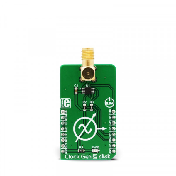
Clock Gen 2 click


- Order number: MIKROE-3076
- Manufacturer product ID: MIKROE-3076
Equipped with the NV memory, synchronous Output Enable and Power Down function, clock prescaler, spread-spectrum options for reducing EMI radiation, the high-quality SMA connector, and an industry-standard I2C communication interface, the Clock Gen 2 click can be used for development and evaluation of various applications that require a reliable and EMI-free clock signal. It can be especially useful when building applications that allow switching of the main MCU, eliminating the need to equip every MCU with its own clock signal generator.
Spread-Spectrum Dithering
Since all the digital signals within a device are synchronous, the high-frequency harmonics generated on the edges of these digital impulses are adding up, resulting with a very large narrow-band peak signal, that can easily exceed the acceptable level. To avoid this, a technique called spread-spectrum dither is employed, which slightly changes the clock rate over time, broadening the harmonics frequency band, preventing all the digital signals and their harmonics within the circuit to resonate (add-up) and cause considerably large EMI. There are several types of spread-spectrum dithering, depending on the frequency modulation waveform, as well as the modulation range and offset.
How does it work?
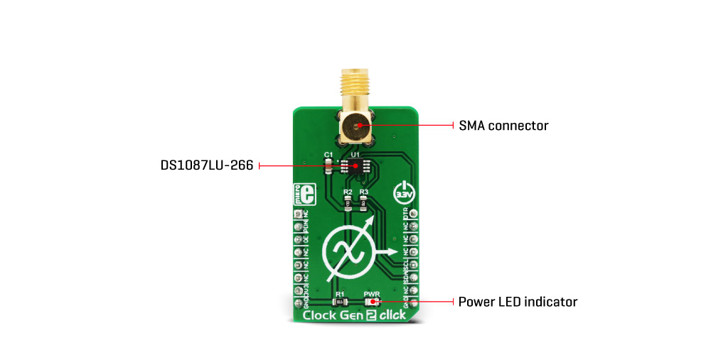
The main component used in the Clock Gen 2 click, is the DS1087LU-266, a 3.3V spread-spectrum EconOscillator, from Maxim Integrated (Dallas Semiconductors). This IC is factory-produced with a range of different master clock frequencies, ranging from 33.3 MHz, up to 66.6 MHz, with variable spread spectrum percentages. The IC used on the Clock Gen 2 click has the master clock fixed to 66.6 MHz, allowing the frequency range from 260 kHz to 66.6 MHz to be achieved. This IC uses the clock prescaler in the range from 2 0 to 2 8 in order to achieve frequencies different from the master frequency. By selecting the spread-spectrum percentage, it is possible to avoid generation of too much EMI, that otherwise might violate the FCC/IEC regulations.
 As already mentioned, the internal clock frequency which is generated by the DS1087LU-266 is 66.6MHz. The master clock is frequency-modulated by the internal triangle wave generator. The main oscillator frequency can be dithered below the maximum frequency by a selectable ratio. A bit in the prescaler register determines the spread-spectrum dither range, which can be selected between 2% and 4% under the main clock frequency. The IC pin labeled as SPRD is routed to the mikroBUS™ PWM pin. A logic HIGH level on this pin enables the spread-spectrum function.
The DS1087LU is equipped with the non-volatile memory locations (EEPROM), used to store the content of all the configuration registers. Writing data to the configuration registers can be automatically mirrored to the EEPROM. This is controlled by the Write Control bit (WC). It allows to either automatically store data to EEPROM after each register change (WC = 0, default), or to store the config data manually, by issuing the WRITE EE command (WC = 1). This feature allows the configuration to be remembered between the POR (Power ON Reset) cycles.
Output Enable (OE) pin allows the output clock to be disabled at the output pin. A logic HIGH level on this pin disables the clock output. However, this will not disable the internal master clock generator, so the IC will still drain the power, necessary to work. To completely put the device in a power down mode, another pin is used: a logic LOW level on the PDN pin shuts down the master oscillator, draining less current from the power source. The OE pin is routed to the mikroBUS™ CS pin and it is labeled as OE, while the PDN pin is routed to the RST pin of the mikroBUS™ and is labeled as PDN. Both of these signals are synchronized with the internal master clock, preventing glitches at the output.
The clock output signal is present at the SMA connector on the Click board™. This connector provides protection of the high-frequency clock signal and further reduces EMI. It also provides a reliable contact with the least possible losses. The clock output signal amplitude is 2.4V, which makes this Click board™ usable with most 3.3V operated MCUs and other devices.
The standardized I2C interface allows this Click board™ to be interfaced with a wide range of devices. I2C clock and data pins of the IC (SCL and SDA) are routed to the appropriate mikroBUS™ pins, allows simple and reliable interfacing.
Specifications
| Type | PWM |
| Applications | For development and evaluation of various applications that require a reliable and EMI-free clock signal. Useful when building applications that allow switching of the main MCU, eliminating the need to equip every MCU with own clock signal generator |
| On-board modules | DS1087LU-266, a 3.3V spread-spectrum EconOscillator, from Maxim Integrated (Dallas Semiconductors) |
| Interface | GPIO,I2C |
| Input Voltage | 3.3V |
| Click board size | M (42.9 x 25.4 mm) |
Pinout diagram
This table shows how the pinout on Clock Gen 2 click corresponds to the pinout on the mikroBUS™ socket (the latter shown in the two middle columns).
| Notes | Pin | Pin | Notes | ||||
|---|---|---|---|---|---|---|---|
| NC | 1 | AN | PWM | 16 | DTR | Dither Enable | |
| Power Down | PDN | 2 | RST | INT | 15 | NC | |
| Output Enable | OE | 3 | CS | RX | 14 | NC | |
| NC | 4 | SCK | TX | 13 | NC | ||
| NC | 5 | MISO | SCL | 12 | SCL | I2C Clock | |
| NC | 6 | MOSI | SDA | 11 | SDA | I2C Data | |
| Power supply | 3.3V | 7 | 3.3V | 5V | 10 | NC | |
| Ground | GND | 8 | GND | GND | 9 | GND | Ground |
Clock Gen 2 click electrical specifications
| Description | Min | Typ | Max | Unit |
|---|---|---|---|---|
| Master Oscillator Frequency Tolerance | -0.5 | - | 0.5 | % |
| I2C clock frequency | - | - | 400 | kHz |
Onboard settings and indicators
| Label | Name | Default | Description |
|---|---|---|---|
| LD1 | PWR | - | Power LED indicator |
| CN1 | CN1 | - | Clock output SMA connector |
Software Support
We provide a library for the ClockGen2 Click on our LibStock page, as well as a demo application (example, developed using MikroElektronika compilers. The demo can run on all the main MikroElektronika development boards.
Library Description
Library provides basic functions for setting different clock output frequencies.
Key functions :
void clockgen2_setPrescaler(uint8_t VAL); - Function for setting the clock prescaler.
void clockgen2_changeAddress(uint8_t _newAddr); - Function for changing the default address.
void clockgen2_outputEnable(uint8_t state); - Function for enabling the clock output.
Examples Description
The application is composed of three sections :
- System Initialization - Initialize GPIO and I2C structures.
- Application Initialization - Driver initialization.
- Application Task - Changes the prescaler and enables/disables the clock output.
void applicationTask()
{
char i;
for( i = 5; i< 8; i++ )
{
clockgen2_setPrescaler(i);
clockgen2_outputEnable(1);
Delay_ms(2000);clockgen2_outputEnable(0);
Delay_ms(2000);
}
}
The full application code, and ready to use projects can be found on our
LibStock page.
Other mikroE Libraries used in the example:
- I2C Library
Additional notes and information
Depending on the development board you are using, you may need USB UART click, USB UART 2 clickor RS232 click to connect to your PC, for development systems with no UART to USB interface available on the board. The terminal available in all MikroElektronika compilers, or any other terminal application of your choice, can be used to read the message.
mikroSDK
This click board is supported with mikroSDK - MikroElektronika Software Development Kit. To ensure proper operation of mikroSDK compliant click board demo applications, mikroSDK should be downloaded from the LibStock and installed for the compiler you are using.