
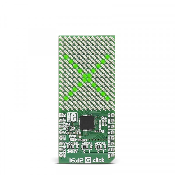
16x12 G click


- Order number: MIKROE-2758
- Manufacturer product ID: MIKROE-2758
16x12 G click carries a 16x12 LED display and the IS31FL3733 matrix driver. The click is designed to run on either 3.3V or 5V power supply. It communicates with the target microcontroller over I2C interface, and the following pins on the mikroBUS™ line: INT, RST, CS.
Each LED can be controlled individually – both for on/off control and light intensity.
IS31FL3733 driver features
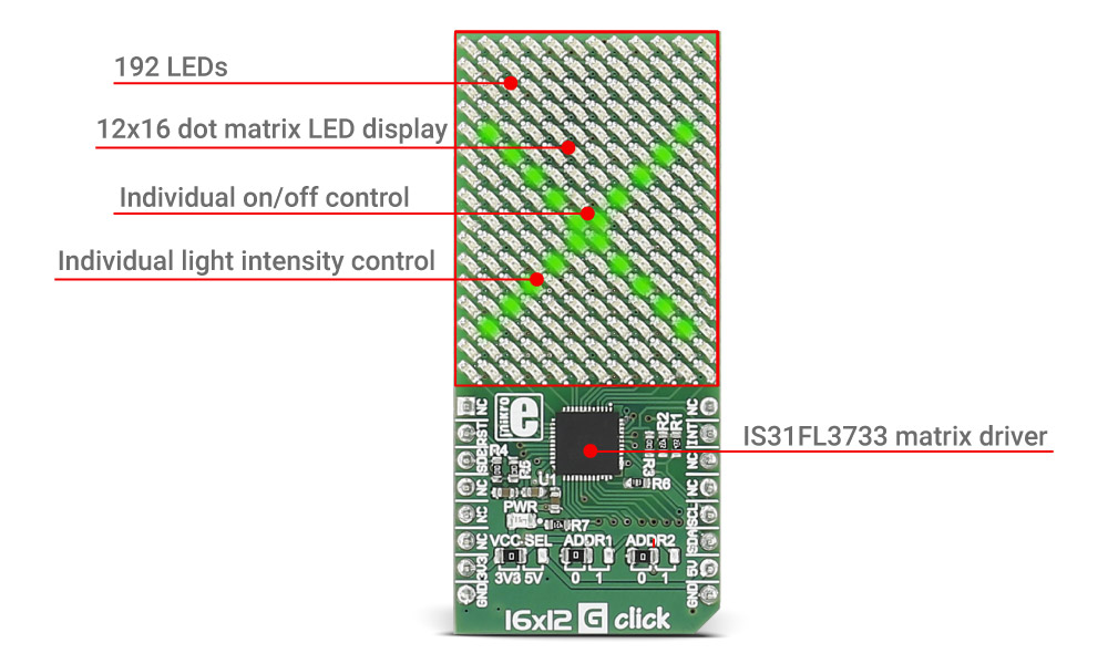
The IS31FL3733 is a general purpose 12×16 LEDs matrix driver with 1/12 cycle rate.
Each of the 192 LEDs can be dimmed individually with 8-bit PWM data, which allows 256 steps of linear dimming.
The driver has selectable 3 Auto Breath Modes for each LED ( ABM-1, ABM-2, and ABM-3).
Specifications
| Type | LED Matrix |
| Applications | Gaming devices, small handheld devices, home appliances, IoT devices, etc. |
| On-board modules | IS31FL3733 matrix driver |
| Key Features | Selectable 3 Auto Breath Modes for each dot, Individual 256 PWM control steps |
| Key Benefits | Each of the 192 LEDs can be dimmed individually |
| Interface | GPIO,I2C |
| Input Voltage | 3.3V or 5V |
| Click board size | L (57.15 x 25.4 mm) |
Pinout diagram
This table shows how the pinout on 16x12 G click corresponds to the pinout on the mikroBUS™ socket (the latter shown in the two middle columns).
| Notes | Pin | Pin | Notes | ||||
|---|---|---|---|---|---|---|---|
| NC | 1 | AN | PWM | 16 | NC | ||
| Reset | RST | 2 | RST | INT | 15 | INT | Interrupt pin |
| Standby | SDB | 3 | CS | TX | 14 | NC | |
| NC | 4 | SCK | RX | 13 | NC | ||
| NC | 5 | MISO | SCL | 12 | SCL | I2C clock | |
| NC | 6 | MOSI | SDA | 11 | SDA | I2C data | |
| Power supply | +3.3V | 7 | 3.3V | 5V | 10 | +5V | Power supply |
| Ground | GND | 8 | GND | GND | 9 | GND | Ground |
Jumpers and settings
| Designator | Name | Default Position | Default Option | Description |
|---|---|---|---|---|
| JP1 | PWR.SEL. | Left | 3V3 | Power Supply Voltage Selection 3V3/5V, left position 3V3, right position 5V |
| JP2 | ADDR. 1 | Left | 0 | The last two bits of the I2C address |
| JP2 | ADDR. 2 | Left | 0 | The last two bits of the I2C address |
Programming
Code examples for 16x12 G click, written for MikroElektronika hardware and compilers are available on Libstock.
Code snippet
The following code snippet shows the default initialization procedure for 16x12 G click board™.
01 IS31FL3733_init( &instance, _IS31FL3733_GND_ADDR, _IS31FL3733_GND_ADDR,
02                      I2C2_Start, I2C2_Stop, I2C2_Write, I2C2_Read );
03     IS31FL3733_setGCC( &instance, 64 );
04     // PWM control mode (default)
05     for( i = 0; i < _IS31FL3733_CS; ++i )
06     {
07         // Set PWM values for all LEDs at i-th row to 55/255 level.
08         IS31FL3733_setLEDPWM ( &instance, i, _IS31FL3733_SW, 55 );
09         // Turn on selected LEDs.
10         IS31FL3733_setLEDState ( &instance, i, _IS31FL3733_SW,
11                                  _IS31FL3733_LED_STATE_ON );
12     }
13     // Clear the matrix
14     IS31FL3733_clearMatrix( &instance );