- Order number: MIKROE-2153
- Manufacturer product ID: MIKROE-2153
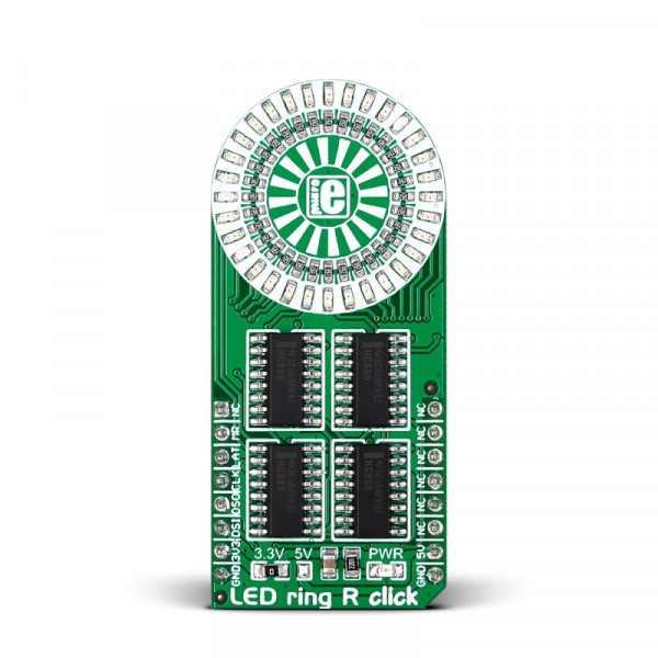
LED ring R click is a mikroBUS™ add-on board with a ring of 32 red LEDs driven by four 8-bit 74HC595 serial-in, parallel-out shift registers. The ring is 25mm in diameter. The click communicates with the target MCU through the mikroBUS™ SPI interface, with RST, CS, SCK, MISO and MOSI pins marked MR#, LAT, CLK, DSOUT, DSIN, respectively. Other LED colors will also be available. The board is designed to use either a 3.3V or 5V power supply only.
Specification
| Type | LED Matrix |
| Applications | Indicator lights or decorative installations |
| On-board modules | 8-bit 74HC595 serial-in, parallel-out shift registers |
| Key Features | Ring of 32 red LEDs, Four 74HC595 registers, 25mm diameter |
| Key Benefits | Using 8-bit shift registers to drive an array of LEDs is simply good practice, because it leaves more available pins on the target MCU |
| Interface | GPIO,SPI |
| Input Voltage | 3.3V or 5V |
| Compatibility | mikroBUS |
| Click board size | L (57.15 x 25.4 mm) |
Features and usage notes
LED ring click is one of several click boards that employ 74HCP595 shift registers to drive LEDs. Rotary click use the same, as well as Bargraph click, 7-Seg click and 7x10 click.
Using 8-bit shift registers to drive an array of LEDs is simply good practice, because it leaves more available pins on the target MCU, allowing you to either use a cheaper, lower pin count main MCU, or use the leftover pins for other purposes.
The end result is a smaller, more cost effective design.
Programming
The following code snippet demonstrates different ways to communicate with the click and initializes a clockwork pattern with a single LED at a time.
1 sbit LRR_LAT at GPIOD_ODR.B13; 2 sbit LRR_RST at GPIOC_ODR.B2; 3 #include4 #include "led_ring_hw.h" 5 6 void main() 7 { 8 9 uint8_t test_bfr[4]; 10 uint8_t i = 0; 11 uint16_t var_time = 500; 12 uint32_t led = 0x00000001; 13 14 // set latch and reset pins as output 15 16 GPIO_Digital_Output(&GPIOD_BASE, _GPIO_PINMASK_13); 17 GPIO_Digital_Output(&GPIOC_BASE, _GPIO_PINMASK_2); 18 19 // initalize SPI 20 21 SPI3_Init_Advanced( _SPI_FPCLK_DIV16, _SPI_MASTER | _SPI_8_BIT | 22 _SPI_CLK_IDLE_LOW | _SPI_FIRST_CLK_EDGE_TRANSITION | 23 _SPI_MSB_FIRST | _SPI_SS_DISABLE | _SPI_SSM_ENABLE | 24 _SPI_SSI_1, &_GPIO_MODULE_SPI3_PC10_11_12); 25 26 led_ring_hal_init(); 27 led_ring_start(); 28 29 test_bfr[0] = 0xAA; 30 test_bfr[1] = 0xAA; 31 test_bfr[2] = 0xAA; 32 test_bfr[3] = 0xAA; 33 34 led_ring_hal_write(&test_bfr, 4); // demonstration of HAL write function 35 led_ring_latch(); 36 37 Delay_ms(1000); 38 39 led_ring_send_32 ( 0xFAFAFAFA ); // demonstration of writing 4 bytes 40 41 Delay_ms(2000); 42 led_ring_send_8 ( test_bfr[0] ); // writing one byte at a time 43 led_ring_send_8 ( test_bfr[0] ); 44 led_ring_send_8 ( test_bfr[0] ); 45 led_ring_send_8 ( test_bfr[0] ); 46 47 while (1) 48 { 49 led_ring_send_32 ( led ); // dot circling faster and faster 50 vDelay_ms(var_time); 51 led = led << 1; 52 if (led == 0) 53 { 54 led = 1; 55 i++; 56 if (i == 0) 57 var_time = 500; 58 else if (i == 1) 59 var_time = 250; 60 else if (i == 2) 61 var_time = 100; 62 else if (i == 3) 63 var_time = 50; 64 else if ( i == 4 ) 65 { 66 var_time = 500; 67 i = 0; 68 } 69 } 70 } 71 }
Code examples that demonstrate the usage of LED Ring click with MikroElektronika hardware, written for mikroC for ARM, PIC, and FT90x are available on Libstock.


