
UT-S 7-SEG R click


- Order number: MIKROE-2840
- Manufacturer product ID: MIKROE-2840
7-segment LED display is the most commonly used type of display to represent changing numerical values. The principle is very simple - seven LED segments are positioned in a certain shape and by turning specific segments on or off, the shape that resembles a specific number is lit. This method of displaying numbers was first used in the beginning of the 20th century, but after the invention of the LED in ‘70, it is the most commonly used method to display numbers. It utilizes a fairly simple and cheap design with the numbers clearly visible. Be it a clock on the nightstand, a billboard at the airport, a gauge on some machine, a panel on some instrument or a display on the pump at the gas station - the numbers will be always easy to see and read, even in the dark.
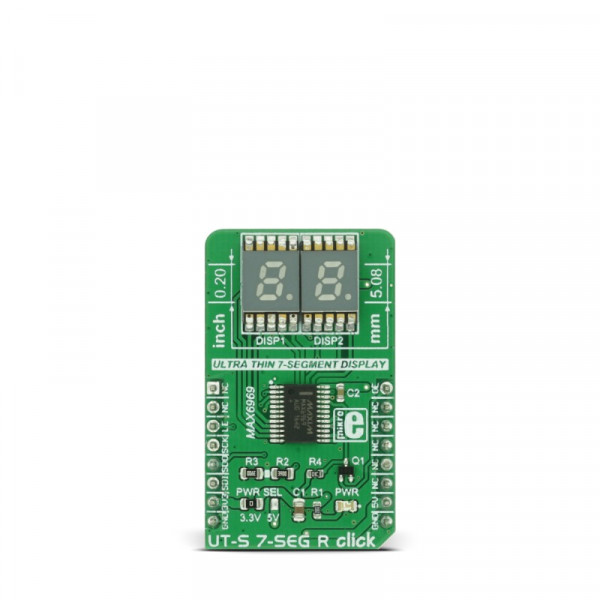
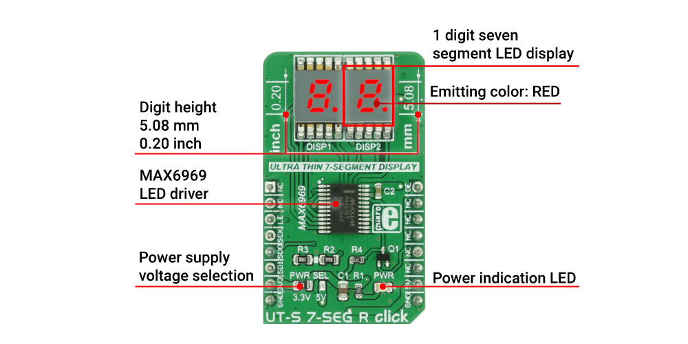
UT-S 7 SEG R click uses two SMD ultra-thin DSM7UA20101 7-SEG LED displays, made with the patented technology that delivers thickness of only 2.1 mm. Those displays are driven by the MAX6969, a constant current LED integrated driver from Maxim Integrated, which uses the SPI serial interface for communication and delivers steady and constant power source for the LED segments.
How does it work?
The UT-S 7 SEG R drives two LED seven segment displays with the MAX6969, a LED driver integrated circuit, built to drive this kind of displays. The current through the segments is set as constant, by the resistor connected between the GND and the SET pin of the IC. In this case, it is kept at around 23 mA, as per segment requirements. The click can work with both 3.3V and 5V, selectable by the PWR SEL jumper.
The used displays are SMD type DSM7UA20101 LED thin displays from VCC company, with medium sized (5.08mm/0.20") numerical characters. The characters can perfectly fit to a smaller dimension housing, and emit a red light.
The click uses the SPI communication lines. The data received via the SPI serial interface is kept inside the internal serial-to-parallel shift register. The reading process happens when the LE (load enable) pin is set to the logic HIGH state. When the LE pin of the click is altered to a logic LOW state, the content of the serial-to-parallel shift register is shifted to the sixteen output latches. The latches are connected to the output pins - from OUT0 to OUT15 respectively, driving the LED segments of the two 7 SEG displays.
Outputs can be additionally turned off and on by the OE pin of the click, routed to the #OE pin of the MAX6969 IC itself. The signal is inverted by the means of the additional NPN transistor, so the logic LOW state of the OE pin will turn off the outputs, regardless of the inverted nature of the #OE pin on the IC itself. The state change on OE pin will not alter the content of the latches, so it can be used to dim the LED segments by applying the PWM signal. For this reason, the OE pin is routed to the PWM pin of the mikroBUS™.
The serial data is also sent out via the SDO pin of the click during the rising edge of the CLK (clock) signal, so daisy chaining of several devices is also possible.
Libraries supported with this click allow for an easy implementation in the code and the included example demonstrates the functionality of the click, using the functions that these libraries provide. The example can also be used as a reference or a starting point for any custom application design.
Specifications
| Type | LED Segment |
| Applications | Displaying characters on two 7 segment displays |
| Displays | Two SMD ultra thin DSM7UA 7-SEG displays, emitting color: RED |
| On-board modules | MAX6969 16-Port, 5.5V Constant-Current LED Driver |
| Key Features | Low power, low profile SMD 7 seg displays, common anode, serial 4-Wire communication, up to 25Mbit/s |
| Interface | PWM,SPI |
| Input Voltage | 3.3V or 5V |
| Click board size | M (42.9 x 25.4 mm) |
Pinout diagram
This table shows how the pinout on UT-S 7-SEG R click corresponds to the pinout on the mikroBUS™ socket (the latter shown in the two middle columns).
| Notes | Pin | Pin | Notes | ||||
|---|---|---|---|---|---|---|---|
| NC | 1 | AN | PWM | 16 | OE | Output-Enable Input | |
| NC | 2 | RST | INT | 15 | NC | ||
| Load-Enable Input | LE | 3 | CS | RX | 14 | NC | |
| Clock Input | SCK | 4 | SCK | TX | 13 | NC | |
| Serial Data Output | SDO | 5 | MISO | SCL | 12 | NC | |
| Serial Data Input | SDI | 6 | MOSI | SDA | 11 | NC | |
| Power Supply | +3.3V | 7 | 3.3V | 5V | 10 | +5V | Power supply |
| Ground | GND | 8 | GND | GND | 9 | GND | Ground |
Onboard settings and indicators
| Label | Name | Default | Description |
|---|---|---|---|
| LD1 | PWR LED | - | Power indication LED |
| JP1 | PWR SEL. | Left | Power supply voltage selection, left position 3V3, right position 5V |
Software support
We provide a library for UT-S 7SEG R click on our LibStock page, as well as a demo application (example), developed using MikroElektronika compilers. The demo can run on all the main MikroElektronika development boards.
Library Description
The library covers all the necessary functions for UT-S 7SEG R click control.
Key functions
uts7segr_writeData- Generic write function
uts7segr_writeNumDec- Writes decimal number
uts7segr_writeNumHex- Writes hexadecimal number
Examples Description
The demo application is composed of three sections:
- System Initialization - Initialize GPIO pins and SPI module for communication with UT 7SEG click.
- Application Initialization - Driver Initialization and turning on the lights by setting PWM pin to logical 1.
- Application Task - Contains four sequences:
- The first sequence shows how to use generic write functions by providing minus and custom.
- The second sequence is a demonstration of the counter using the function for decimal numbers.
- The third sequence is a demonstration of the counter using the function for hexadecimal numbers.
- The fourth sequence is a demonstration of the counter using a function with dot option.
NOTE: Brightness can be adjusted using the MCUs PWM module. In that case, GPIO setup for PWM pin is not necessary.
void applicationTask()
{
uts7segr_writeData( _UTS7SEGR_MINUS, 0xFF );
counter = 0;
while (counter < 3)
{
uts7segr_lightCtl( 0 );
Delay_ms( 200 );
uts7segr_lightCtl( 1 );
Delay_ms( 300 );
counter++;
}
counter = 0;
while (counter < 100)
{
uts7segr_writeNumDec( counter );
Delay_ms(100);
counter++;
}
counter = 0;
while (counter < 0xFF)
{
uts7segr_writeNumHex( counter );
Delay_ms(100);
counter++;
}
counter = 0;
while (counter < 100)
{
uts7segr_writeNumDot( counter, _UTS7SEGR_DOT_L );
Delay_ms(100);
counter++;
}
}
The full application code, and ready to use projects can be found on our LibStock page.
mikroSDK
This click board is supported with mikroSDK, the MikroElektronika Software Development Kit. To download mikroSDK visit LibStock. For more information about SDK, visit the official page.