
Hz to V click


- Order number: MIKROE-2890
- Manufacturer product ID: MIKROE-2890
Frequency-to-voltage converter with a linear response
HZ to V click is a device that can convert input frequency of the signal with virtually any wave shape to a DC voltage output, with a level proportional to the input frequency. It has a linear response, and by applying a signal with the frequency between 10Hz and 10kHz on its input, the Click board™ will generate a DC voltage, ranging from 0V to 3.3V. Hz to V click features very good linearity, covers a wide input frequency range from 10Hz to 10kHz and it has good temperature stability.
These features allow this device to be used in various frequency to voltage applications: in instrumentation, industrial, and automation markets. It is well suited for use in AD conversion, long-term integration, frequency to voltage conversion, RPM measurement, frequency demodulation and similar applications which can benefit from an accurate and reliable frequency to voltage conversion.
How does it work?
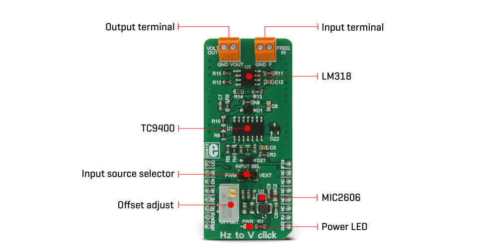
The main component of the Hz to V click is the TC9400, a voltage-to-frequency and frequency-to-voltage converter from Microchip. It accepts a signal with the frequency within a range between 10Hz and 10kHz on the input and generates DC voltage with the level corresponding to the input frequency, ranging from 0V to 10V, with a highly linear response. This signal is further passed through the operational amplifier, in order to scale it down to a level acceptable by the MCU. The input signal can be applied either to the PWM pin of the mikroBUS™ or the external input terminal. The input source can be selected with the onboard switch, labeled as INPUT SEL.
When Hz to V click is operated for the first time, it needs to be calibrated. The click is equipped with a variable resistor for the offset fine tuning. The following procedure should be followed to calibrate the device:
- An input signal with a frequency of 10Hz should be applied to the input. The offset should be adjusted so that a 10mV DC signal appears on the output.
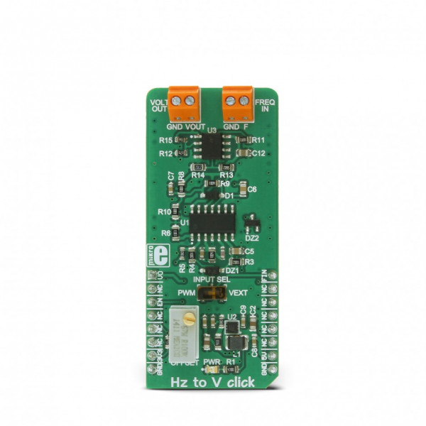
HZ to V click is equipped with the input signal terminal (FREQ IN), which is used to connect the signal with a frequency which is in the acceptable range between 10Hz and 10kHz. Besides this signal input terminal, it is possible to select the PWM signal generated by the host MCU as the input, too. INPUT SEL switch can be set so that the PWM pin from the mikroBUS™ is used as the control voltage input. It is recommended that the signal amplitude does not exceed 3.3V.
The output terminal (VOLT OUT) is used to output the generated voltage. As already explained, the voltage level depends on the input signal frequency. This generated voltage is also available on the AN pin of the mikroBUS™. The output signal is passed through the operational amplifier (OPAMP) which is used both as the output buffer and a voltage adjust stage for the output voltage. A well known general purpose operational amplifier LM318 from Texas Instruments is used for this purpose.
To provide 12V for the TC9400 and the LM318 OPAMP, Hz to V click employs a boost converter built around the MIC2606, a boost regulator from Microchip, which works at 2MHz. This IC provides 12V for supplying the TC9400 out of 5V routed from the mikroBUS™ socket. The EN pin of the boost regulator is routed to the mikroBUS™ CS pin and it is used to enable power output from the boost regulator, effectively enabling the TC9400 itself. The EN pin is pulled to a HIGH logic level (3.3V) by the onboard resistor.
Specifications
| Type | Measurements |
| Applications | Hz to V is well suited for use in AD conversion, long-term integration, frequency to voltage conversion, RPM measurement, frequency demodulation and similar applications which can benefit from an accurate and reliable frequency to voltage conversion. |
| On-board modules | TC9400 Voltage-to-Frequency / Frequency-to-Voltage Converters, MIC2605/6 a 1.2MHz/2MHz, PWM DC/DC Boost Switching Regulator, both from Microchip, LM318, a dual opamp from Texas Instruments |
| Key Features | Hz to V click features very good linearity, covers a frequency range from 10Hz to 10kHz and it has good temperature stability. |
| Input Voltage | 3.3V,5V |
| Click board size | L (57.15 x 25.4 mm) |
Pinout diagram
This table shows how the pinout on Hz to V click corresponds to the pinout on the mikroBUS™ socket (the latter shown in the two middle columns).
| Notes | Pin | Pin | Notes | ||||
|---|---|---|---|---|---|---|---|
| Voltage Out | VO | 1 | AN | PWM | 16 | FIN | Frequency In |
| NC | 2 | RST | INT | 15 | NC | ||
| Chip Enable | EN | 3 | CS | RX | 14 | NC | |
| NC | 4 | SCK | TX | 13 | NC | ||
| NC | 5 | MISO | SCL | 12 | NC | ||
| NC | 6 | MOSI | SDA | 11 | NC | ||
| Power Supply | +3.3V | 7 | 3.3V | 5V | 10 | +5V | Power Supply |
| Ground | GND | 8 | GND | GND | 9 | GND | Ground |
Onboard settings and indicators
| Label | Name | Default | Description |
|---|---|---|---|
| LD1 | PWR | - | Power indication LED |
| TB1 | FREQ IN | - | Frequency input terminal |
| TB2 | VOLT OUT | - | Voltage output terminal |
Hz to V click electrical specifications
| Description | Min | Typ | Max | Unit |
|---|---|---|---|---|
| Input Signal Amplitude | - | 3.3 | - | V |
| Input Frequency | 10 | - | 10,000 | Hz |
| Output Voltage Level | 0 | - | 3.3 | V |
Software support
We provide a library for Hz to V click on our LibStock page, as well as a demo application (example), developed using MikroElektronika compilers and mikroSDK. The provided click library is mikroSDK standard compliant. The demo application can run on all the main MikroElektronika development boards.
Examples Description
The demo application shows how to control the Hz to V click using MCU's PWM module.
The demo application is composed of two sections:
- Application Task - Alternates between different output voltages.
- hz2v_setOutputVoltage - Sets the PWM frequency to the required value, changing the
output voltage.
//Sets the output voltage in millivolts
void hz2v_setOutputVoltage(uint16_t voltage)
{
pwmPeriod = PWM_TIM5_Init(voltage*2);
PWM_TIM5_Set_Duty(pwmPeriod/2, _PWM_NON_INVERTED, _PWM_CHANNEL1);
PWM_TIM5_Start(_PWM_CHANNEL1, &_GPIO_MODULE_TIM5_CH1_PA0);
}
void applicationTask()
{
hz2v_setOutputVoltage(5000); //5 V output
Delay_ms(3000);
hz2v_setOutputVoltage(2500); //2.5 V output
Delay_ms(3000);
hz2v_setOutputVoltage(1000); //1 V output
Delay_ms(3000);
hz2v_setOutputVoltage(500); //0.5 V output
Delay_ms(3000);
}
The full application code, and ready to use projects can be found on our LibStock page.
Other MikroElektronika Libraries used in the example:
- PWM
Additional notes and information
Depending on the development board you are using, you may need USB UART click, USB UART 2 click or RS232 click to connect to your PC, for development systems with no UART to USB interface available on the board. The terminal available in all MikroElektronika compilers, or any other terminal application of your choice, can be used to read the message.
mikroSDK
This click board is supported with mikroSDK - MikroElektronika Software Development Kit. To ensure proper operation of mikroSDK compliant click board demo applications, mikroSDK should be downloaded from the LibStock and installed for the compiler you are using.