
V to Hz click


Prices incl. VAT plus shipping costs
Ready to ship today,
Delivery time appr. 1-3 workdays
- Order number: MIKROE-2889
- Manufacturer product ID: MIKROE-2889
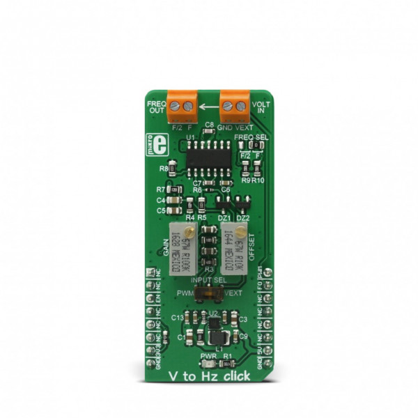
V to HZ click is a device that converts an analog voltage input signal into a pulse wave signal of a certain frequency. It has a linear response, so applying a voltage in a range of 0 to 5V on its input, will result in generating the pulse train with frequency linearly proportional to the input voltage. This click features very good linearity, covers a frequency range from 10Hz to 10 kHz and it has a good temperature stability.
These features allow this device to be used in various voltage to frequency applications: it can be used in various applications in instrumentation, industrial, and automation markets. It is well suited for use in AD conversion, long-term integration, linear frequency modulation, voltage-to-frequency conversion and it can be used as the variable clock signal generator.
How does it work?
The main component of the V to HZ click is the TC9400, a voltage-to-frequency and frequency-to-voltage converter from Microchip. It accepts voltage at its input and generates a pulse train, with a frequency linearly proportional to the input voltage. The pulse train is present on two output pins: the full frequency pin outputs signal with the pulse rate linear to the input voltage, while the half frequency pin outputs signal with the pulse rate equal to the half of the full frequency pin pulse rate.
When V to Hz click is operated for the first time, it needs to be calibrated. The click is equipped with two variable resistors for gain and offset fine tuning. There are several steps that should be followed when calibrating:
- An input signal of 10mV should be applied to the input. The offset should be adjusted so that a 10Hz signal appears on the output
- An input signal of 5V should be applied to the input. The gain should be adjusted so that 10kHz signal appears on the output
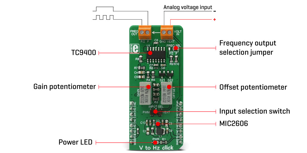
V to HZ click is equipped with the input voltage terminal (VOLT IN), which is used to connect the control voltage up to 5V. Besides having control voltage input on this terminal, it is possible to select the voltage generated by the MCU as the control voltage input, too. INPUT SEL switch can be set so that the PWM pin from the mikroBUS™ is used as the control voltage input. The PWM signal generated by the MCU is filtered out by the onboard low pass filter so that the control voltage remains constant. For this reason, PWM signal frequency from the MCU should be at least 40 kHz.
The output terminal (FREQ OUT) is used to output the generated frequency. There are two outputs routed to this two-pole screw terminal: the first output is full frequency output (f), while the second output is the half of the generated frequency (f/2). The frequency output is also routed to the INT pin of the mikroBUS™. To select between the half and the full frequency output routed to the INT pin, the FREQ SEL SMD jumper needs to be switched to the correct position. Both of the half frequency and the full frequency outputs are pulled HIGH (3.3V) with an onboard resistor, which means that the output generated signal amplitude will be 3.3V.
To provide 12V for the TC9400, V to Hz click employs a boost converter, built around the MIC2606, a boost regulator from Microchip, which works at 2MHz. This IC provides 12V for supplying the TC9400 out of 5V routed from the mikroBUS™ socket. EN pin of the boost regulator is routed to the mikroBUS™ CS pin and it is used to enable power output from the boost regulator, effectively enabling the TC9400 itself. EN pin is pulled to a HIGH logic level (3.3V) by the onboard resistor.
Specifications
| Type | Measurements |
| Applications | V to Hz click can be used in various applications in instrumentation, industrial and automation markets. It is well suited for use in AD conversion, long-term integration, linear frequency modulation and demodulation, and frequency-to-voltage conversion. |
| On-board modules | TC9400, a voltage-to-frequency and frequency-to-voltage converter from Microchip, and MIC2606, a PWM DC/DC boost switching regulator from Microchip. |
| Key Features | V to Hz click features very good linearity, covers a frequency range from 10Hz to 10 kHz and it has a good temperature stability. |
| Interface | GPIO |
| Input Voltage | 3.3V,5V |
| Click board size | L (57.15 x 25.4 mm) |
Pinout diagram
This table shows how the pinout on V to HZ click corresponds to the pinout on the mikroBUS™ socket (the latter shown in the two middle columns).
| Notes | Pin | Pin | Notes | ||||
|---|---|---|---|---|---|---|---|
| NC | 1 | AN | PWM | 16 | PWM | PWM input | |
| NC | 2 | RST | INT | 15 | FO | Frequency Output | |
| Boost Regulator Enable | EN | 3 | CS | RX | 14 | NC | |
| NC | 4 | SCK | TX | 13 | NC | ||
| NC | 5 | MISO | SCL | 12 | NC | ||
| NC | 6 | MOSI | SDA | 11 | NC | ||
| Power Supply | +3.3V | 7 | 3.3V | 5V | 10 | +5V | Power Supply |
| Ground | GND | 8 | GND | GND | 9 | GND | Ground |
V to HZ click electrical specifications
| Description | Min | Typ | Max | Unit |
|---|---|---|---|---|
| Input Voltage | 0 | 5 | V | |
| Output Frequency | 10 | 10,000 | Hz | |
| Output Signal Amplitude | 3.3 | V |
Onboard settings and indicators
| Label | Name | Default | Description |
|---|---|---|---|
| LD1 | PWR | - | Power LED indicator |
| JP1 | FREQ SEL | Right | Selects the frequency output routed to the mikroBUS™ INT pin: left position - half frequency output (f/2), right position - full frequency output (f). |
| SW1 | INPUT SEL | - | Selects the input voltage source: left position - PWM pin from the mikroBUS™, right position - VEXT voltage from the terminal input. |
Software support
We provide a library for V to Hz click on our LibStock page, as well as a demo application (example), developed using MikroElektronika compilers. The provided click library is mikroSDK standard compliant. The demo application can run on all the main MikroElektronika development boards.
Examples Description
The demo application is composed of the application task, and set frequency function :
- Application Task - Alternates between different output frequencies
- v2hz_setOutputFrequency - Sets the PWM duty cycle to required value, changing
v2hz_setOutputFrequency(float frequency)
{
float dutyCycle;
dutyCycle = PWM_TIM5_Init(50000);
dutyCycle *= frequency;
dutyCycle /= 10000;
PWM_TIM5_Set_Duty(dutyCycle,  _PWM_NON_INVERTED, _PWM_CHANNEL1);
PWM_TIM5_Start(_PWM_CHANNEL1, &_GPIO_MODULE_TIM5_CH1_PA0);
}
void applicationTask()
{
v2hz_setOutputFrequency(1000);        //1000 Hz output
Delay_ms(3000);
v2hz_setOutputFrequency(2000);        //2000 Hz output
Delay_ms(3000);
v2hz_setOutputFrequency(5000);        //5000 Hz output
Delay_ms(3000);
v2hz_setOutputFrequency(10000);       //10000 Hz output
Delay_ms(3000);
}
The full application code, and ready to use projects can be found on our LibStock page.
Other MikroElektronika libraries used in the example:
- PWM
Additional notes and information
Depending on the development board you are using, you may need USB UART click, USB UART 2 click or RS232 click to connect to your PC, for development systems with no UART to USB interface available on the board. The terminal available in all MikroElektronika compilers, or any other terminal application of your choice, can be used to read the message.