
Analog Key Click


- Order number: MIKROE-3409
- Manufacturer product ID: MIKROE-3409
Featuring six high-quality pushbuttons, a simple debouncing circuit, and the output op-amp buffer, this Click board™ is an ideal solution for different applications controlled by discrete voltage levels, but also for applications which have restricted number of free pins. This type of keyboard can be used as password terminals for small alarm systems, for selecting an option in various embedded applications, and for all kinds of small DIY projects where low pin count is a big concern.
How Does It Work?
As already mentioned, the working principle of this Click board™ is very simple: it contains a voltage divider, formed by six 1 k? resistors. Those resistors are connected in series, and each connection point is routed to one pin of the SPST pushbutton. The KMR2 series KMR221 tactile buttons are high-quality SPST switches produced by CKSwitches, a company specialized in production of various types of quality switches. These buttons are rated to endure up to 300,000 switching cycles and have very low ON resistance of less than 100 m?. The buttons are rubberized and have a pleasant tactile feel when pressed.
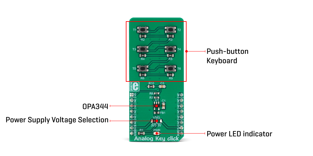
By pressing a button, the respective connection point becomes redirected to the input of the OPA344, a low-power operational amplifier from Texas Instruments, which is configured to work with the unity gain, forming a buffer for the input of the microcontroller (MCU). This prevents changes of the impedance at the MCU input pin, as well as a limited amount of ESD protection.
By substituting the voltage divider resistors with two equivalent resistances (RE1 for the upper set of resistors, and RE2 for the lower set of resistors) the principle can be understood even better: when the top button is pressed (T1), the equivalent RE1 resistance will be 0 ?, so regardless of the RE2 resistance, the voltage at the AN pin will be equal to VCC. When the second button (T2) is pressed, the equivalent RE1 resistance will be 1 k?, while the RE2 resistance will be 5K. The voltage at the AN pin can now be easily calculated by using the simple voltage divider formula:
VOUT=VCC ? RE2 / (RE1+RE2)
RE1 will be 2 k?, and RE2 will be 4 k? when the third (T3) button is pressed, and so on. Following this principle, the discrete voltage level for each button can be easily calculated, depending on the value of the VCC.
The VCC voltage for the voltage divider can be selected using the SMD jumper on the Click board™, labeled as VSEL. This jumper selects either a 3.3V or 5V mikroBUS™ power rail as the VCC source. Since there are many MCUs that cannot tolerate 5V on their pins, the VSEL position is set to 3.3V by default. However, if the 5V operation is required for specific application, it is enough to move the position of the VSEL jumper to the 5V position.
The selected output voltage appears at the AN pin of the mikroBUS™, labeled as VO on Analog Key click. It can be then sampled by the A/D converter of the MCU and used to control a device. Since Analog Key click requires just a single pin for its operation, it is perfectly suited for applications where the pin count restriction is a big problem.
Specifications
| Type | Button |
| Applications | It is an ideal solution for different applications controlled by discrete voltage levels, but also for applications which have restricted number of free pins including password terminals for small alarm systems, for selecting an option in various embedded applications, and for all kinds of small DIY projects where low pin count is a big concern. |
| On-board modules | KMR221, a tactile push-button by CKSwitches; OPA344, a low-power operational amplifier from Texas Instruments. |
| Key Features | Analog keyboard requires a single MCU pin, high quality buffer op-amp, rubberized tactile pushbuttons with very high endurance and low ON resistance, and more. |
| Interface | Analog |
| Input Voltage | 3.3V,5V |
| Click board size | L (57.15 x 25.4 mm) |
Pinout Diagram
This table shows how the pinout on Analog Key Click corresponds to the pinout on the mikroBUS™ socket (the latter shown in the two middle columns).
| Notes | Pin | Pin | Notes | ||||
|---|---|---|---|---|---|---|---|
| Key Voltage OUT | VO | 1 | AN | PWM | 16 | NC | |
| NC | 2 | RST | INT | 15 | NC | ||
| NC | 3 | CS | RX | 14 | NC | ||
| NC | 4 | SCK | TX | 13 | NC | ||
| NC | 5 | MISO | SCL | 12 | NC | ||
| NC | 6 | MOSI | SDA | 11 | NC | ||
| Power Supply | +3V3 | 7 | 3.3V | 5V | 10 | +5V | Power Supply |
| Ground | GND | 8 | GND | GND | 9 | GND | Ground |
Onboard Setting And Indicators
| Label | Name | Default | Description |
|---|---|---|---|
| LD1 | PWR | - | Power LED indicator |
| JP1 | VSEL | Left | Power supply voltage selection: left position 3.3V, right position 5V |
Software Support
We provide a library for the Analog Key Click on our LibStock page, as well as a demo application (example), developed using MikroElektronika compilers. The demo can run on all the main MikroElektronika development boards.
Library Description
The library contains a function which, based on the ADC value, detects which button is pressed.
Key functions:
uint8_t analogkey_getKey(uint16_t adcValue)- Detects which button is pressed.
Examples description
The application is composed of the three sections :
- System Initialization - LOG initialization for displaying data on USB UART.
- Application Initialization - Initializes ADC init.
- Application Task - (code snippet) - Reads ADC value and detects which button is pressed based on that value.
void applicationTask()
{
uint16_t ADC_value;
uint8_t isKey;
char demoText[ 50 ];
uint8_t cnt;
uint16_t sumValue = 0;
for(cnt = 0; cnt < 5; cnt++)
{
ADC_value = analogkey_adcRead();
sumValue += ADC_value;
Delay_10ms();
}
ADC_value = sumValue / 5;
isKey = analogkey_getKey(ADC_value);
if(isKey != _ANALOGKEY_NO_TOUCH)
{
IntToStr(isKey, demoText);
mikrobus_logWrite("Pressed the button : ", _LOG_TEXT);
mikrobus_logWrite(demoText, _LOG_LINE);
}
Delay_ms( 300 );
}
The full application code, and ready to use projects can be found on our LibStock page.
Other mikroE Libraries used in the example:
ADCUART
Additional notes and informations
Depending on the development board you are using, you may need USB UART click, USB UART 2 click or RS232 click to connect to your PC, for development systems with no UART to USB interface available on the board. The terminal available in all MikroElektronika compilers, or any other terminal application of your choice, can be used to read the message.