
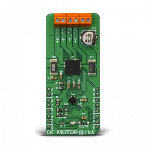
DC MOTOR 7 Click


- Order number: MIKROE-3289
- Manufacturer product ID: MIKROE-3289
Equipped with the specialized motor driver IC, DC MOTOR 7 click can be used for any application that requires a simple and reliable dual DC motor support, including various RC cars and boats, small to medium-sized robots, drones, and similar applications. However, it can also be used for driving DC brushed motors in some more demanding applications, including air or water pumps, air condition systems, ventilation systems, handheld tools, etc.
How does it work?
The main component of DC MOTOR 7 click is the TB67H400AFTG, a PWM chopper-type brushed DC motor driver, produced by Toshiba. This IC uses a proprietary BiCD manufacturing process, allowing this IC to be powered by a wide range of supply voltages, from 10V up to 47V. Due to a very low ON resistance of the MOSFETs, it can theoretically deliver up to 4A of current to the connected load. However, many external parameters affect both the maximum voltage and the current specifications, especially when the connected load is of a complex nature, such as the DC motor. This IC offers an additional, alternative mode, where it can use its internal H-Bridges in parallel, offering twice as much power for a single motor. Before attempting to connect a single DC brushed motor, please refer to the datasheet of the TB67H400AFTG for precise connection instructions.
.jpg)
DC MOTOR 7 click requires an external power supply for operation. The optimal voltage that should be used is 24V. Although the TB67H400AFTG driver has both thermal and overcurrent protection, it is just a temporary measure. A short-circuit at the output terminal may damage the Click board™. There are two output terminals used to connect DC motors, and a power supply input terminal, where the external PSU can be connected, with respect to the polarity marked on the Click board™ itself (bottom side).
Brushed DC motors are typically made with only two conductors, used to supply the motor with power, so even controlling the direction can be challenging in some situations. Therefore, a specialized driver circuit is required. The TB67H400AFTG utilizes two sensing resistors (one for each channel) in combination with an internally generated PWM signal, to regulate the current through the motor. This results in better efficiency, less heat dissipation, and provides control over the torque, direction, and speed of the motor.
Each motor is driven by the internal H-Bridge, which is controlled by the control logic section of the TB67H400AFTG IC. The motor control logic section regulates the current by opening and closing the specific MOSFETs of the H-Bridge, allowing the current through the coils to rise to a certain point (charging), to circulate between the coils and the driver until a specified point of time is reached (slow decay), and then to return the remaining energy to the power supply (fast decay). The whole cycle is timed by pulses of the PWM signal, which is derived from the internal oscillator.
The TB67H400AFTG exposes six control pins to the microcontroller (MCU): PWMA, PWMB, INA1, INA2, INB1, INB2. By changing logic states on these pins, the MCU can control both connected motors, independently. Besides a detailed explanation of the operating modes, the TB67H400AFTG datasheet also provides a truth table that explains the effects of logic states on these pins.
Since the TB67H400AFTG IC has six different control pins, an additional port expander IC is required to allow access to all these pins. PWMA and PWMB pins are routed to the mikroBUS™ RST and PWM pins respectively, while the rest of control pins (INA1, INA2, INB1, and INB2) are accessible via the PCA9538A, an 8-bit I2C port expander by NXP Semiconductors. In addition, the HBMODE pin used to select the single or dual operating mode (Large Mode or Small Mode), as well as the TBLKAB pin used to set the blanking interval, are also available over the PCA9538A IC. Logic states on the PCA9538A pins can be easily set over the I2C interface, allowing to quickly change states on all the control pins of the TB67H400AFTG IC by using a single command over the I2C interface. Please note that the state of the HBMODE pin should not be altered, once the Click board™ is powered up and initialized.
The slave I2C address of the PCA9538A can be changed. Two LSB of the I2C address can be set to 0 or 1, by switching SMD jumpers on the Click board™. This allows four different 7-bit I2C addresses to be selected, in the range from 0x70 to 0x73. The voltage level of logic signals can also be selected by switching the SMD jumper on the Click board™ to either 3V3 or 5V position.
Specifications
| Type | DC |
| Applications | Usable for various RC cars and boats, small to medium-sized robots, drones, and similar applications. as well as for driving motors in air or water pumps, air conditioners, ventilation systems, handheld tools, etc. |
| On-board modules | TB67H400AFTG, a PWM chopper-type brushed DC motor driver, by Toshiba; PCA9538A, an 8-bit I2C port expander by NXP Semiconductors |
| Key Features | Complete DC brushed motor driving solution with reasonably high current capability, a wide range of power supply voltages supported, it can be used in a single or dual configuration, can be controlled via the I2C interface |
| Interface | GPIO,I2C |
| Input Voltage | 3.3V or 5V |
| Compatibility | mikroBUS |
| Click board size | L (57.15 x 25.4 mm) |
Pinout diagram
This table shows how the pinout on DC MOTOR 7 Click corresponds to the pinout on the mikroBUS™ socket (the latter shown in the two middle columns).
| Notes | Pin | Pin | Notes | ||||
|---|---|---|---|---|---|---|---|
| NC | 1 | AN | PWM | 16 | PWMB | PWMB Ctrl IN | |
| PWMA Ctrl IN | PWMA | 2 | RST | INT | 15 | NC | |
| NC | 3 | CS | RX | 14 | NC | ||
| NC | 4 | SCK | TX | 13 | NC | ||
| NC | 5 | MISO | SCL | 12 | SCL | I2C Clock | |
| NC | 6 | MOSI | SDA | 11 | SDA | I2C Data | |
| Power Supply | 3V3 | 7 | 3.3V | 5V | 10 | 5V | Power Supply |
| Ground | GND | 8 | GND | GND | 9 | GND | Ground |
Onboard settings and indicators
| Label | Name | Default | Description |
|---|---|---|---|
| LD1 | PWR | - | Power LED indicator |
| JP1 - JP2 | - | Left | PCA9538A I2C slave address LSB selection: left position 1, right position 0 |
| JP4 | - | Left | Logic voltage level selection: left position 3.3V, right position 5V |
| TB1 | - | - | Motor B output terminal |
| TB2 | - | - | Power supply input terminal |
| TB3 | - | - | Motor A output terminal |
Software support
We provide a library for the DC MOTOR 7 Click on our LibStock page, as well as a demo application (example), developed using MikroElektronika compilers. The demo can run on all the main MikroElektronika development boards.
Library Description
Library offers a choice to get a 10bit result from the AD converter as one sample result or averaged result with the desired number of samples. The result from the ADC can be calculated to get current in a proper value [mA], depending on the RSENSE, ROUT, and VREF on the Current 2 Click board. For more details check the documentation.
Key functions:
void dcmotor7_setMotor(uint8_t motor, uint8_t in1, uint8_t in2)- Functions for set Motor.void dcmotor7_setTBLKAB(uint8_t tBLK)- Functions for set Motor Ach and Bch Digital tBLK.void dcmotor7_setHBMode(uint8_t mode)- Functions for set H-Bridge operation mode.
Examples description
The application is composed of the three sections :
- System Initialization - Initializes I2C module and sets RST pin and PWM pin as OUTPUT.
- Application Initialization - Initialization driver init, enabled all output port, sets H-Bridge operation mode and Motor Digital tBLK.
- Application Task - (code snippet) - Set the motor A and the motor B to rotate clockwise and in the Counterclockwise direction, and between the change of direction, the motor stops the motor.
- note VM input - 10 V (min) to 47 V (max)
void applicationTask()
{
dcmotor7_setMotor(_DCMOTOR7_MOTOR_A, 0, 1);
dcmotor7_setMotor(_DCMOTOR7_MOTOR_B, 0, 1);
Delay_ms( 500 );
dcmotor7_motorStop(_DCMOTOR7_MOTOR_A);
dcmotor7_motorStop(_DCMOTOR7_MOTOR_B);
Delay_ms( 2000 );
dcmotor7_setMotor(_DCMOTOR7_MOTOR_A, 1, 0);
dcmotor7_setMotor(_DCMOTOR7_MOTOR_B, 1, 0);
Delay_ms( 500 );
dcmotor7_motorStop(_DCMOTOR7_MOTOR_A);
dcmotor7_motorStop(_DCMOTOR7_MOTOR_B);
Delay_ms( 2000 );
}
The full application code, and ready to use projects can be found on our LibStock page.
Other mikroE Libraries used in the example:
I2C
Additional notes and information
Depending on the development board you are using, you may need USB UART click, USB UART 2 click or RS232 click to connect to your PC, for development systems with no UART to USB interface available on the board. The terminal available in all MikroElektronika compilers, or any other terminal application of your choice, can be used to read the message.
mikroSDK
This Click board™ is supported by mikroSDK - MikroElektronika Software Development Kit. To ensure the proper operation of the included demo application, the mikroSDK library should be downloaded from LibStock and installed for the used compiler.