
MCP73213 click


- Order number: MIKROE-2575
- Manufacturer product ID: MIKROE-2575
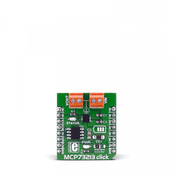
MCP73213 click carries the MCP73213 dual-cell Li-Ion/Li-Polymer battery charge management controller with input overvoltage protection from Microchip. The click is designed to run on either 3.3V or 5V power supply. It communicates with the target microcontroller over SPI.
Note: The click is designed to charge a dual-cell Li-Ion/Li-Polymer battery. The input voltage needs to be higher that the voltage of a dual-cell Li-Ion/Li-Polymer battery.
.jpg)
MCP73213 controller features
The MCP73213 is a highly integrated Li-Ion battery charge management controller.
The MCP73213 provides specific charge algorithms for dual-cell Li-Ion/Li-Polymer batteries to achieve optimal capacity and safety in the shortest charging time possible.
The absolute maximum voltage, up to 18V, allows the use of MCP73213 in harsh environments, such as low-cost wall wart or voltage spikes from plug/unplug.
An internal overvoltage protection (OVP) circuit monitors the input voltage and keeps the charger in shutdown mode when the input supply rises above the typical 13V OVP threshold. The OVP hysteresis is approximately 150 mV for the MCP73213 device.
How it works
First you need to connect the input voltage to the input screw terminal. Then to set the input voltage, because it needs to be larger than voltage of two series connected batteries for regular charging, (which means it needs to be >8V). We can change the charging current trough SPI interface.
Now just leave the batteries to charge, and when they are charged it will be signalized on the status LED.
Specifications
| Type | Battery charger |
| Applications | Portable Media players, digital camcorders, handheld devices, etc. |
| MCU | MCP73213 |
| Key Features | 13V Input Overvoltage Protection, Resistor Programmable Fast Charge Current: 130 mA-1100 mA, Elapse Safety Timer: 4 hr, 6 hr, 8 hr or Disable |
| Interface | SPI |
| Input Voltage | 3.3V or 5V |
| Compatibility | mikroBUS |
| Click board size | S (28.6 x 25.4 mm) |
Pinout diagram
This table shows how the pinout on MCP73213 click corresponds to the pinout on the mikroBUS™ socket (the latter shown in the two middle columns).
| Notes | Pin | Pin | Notes | ||||
|---|---|---|---|---|---|---|---|
| NC | 1 | AN | PWM | 16 | NC | ||
| NC | 2 | RST | INT | 15 | NC | ||
| Chip Select | SPI_CS | 3 | CS | TX | 14 | NC | |
| SPI Clock | SPI_SCK | 4 | SCK | RX | 13 | NC | |
| NC | 5 | MISO | SCL | 12 | NC | ||
| SPI Master output slave input | SPI_MOSI | 6 | MOSI | SDA | 11 | NC | |
| Power supply | +3.3V | 7 | 3.3V | 5V | 10 | +5V | Power supply |
| Ground | GND | 8 | GND | GND | 9 | GND | Ground |
Maximum ratings
| Description | Min | Typ | Max | Unit |
|---|---|---|---|---|
| Input Voltage Range | 4 | 16 | V | |
| Operating Supply Voltage | 4.2 | 13 | V | |
| Fast Change Current Regulation | 130 | 1100 | A |
Programming
Code examples for MCP73213 click, written for MikroElektronika hardware and compilers are available on Libstock.
Code snippet
The following code snippet shows how to initialize the SPI interface, and then use it to set output current to 250mA.
01 void main() {
02
03      /*Sets chip select*/
04      GPIO_Digital_Output (&GPIOD_BASE, _GPIO_PINMASK_13);
05
06      GPIO_Alternate_Function_Enable(&_GPIO_MODULE_SPI3_PC10_11_12);
07      /*Initializes SPI interface*/
08      SPI3_Init_Advanced(_SPI_FPCLK_DIV256, _SPI_MASTER | _SPI_16_BIT |
09        _SPI_CLK_IDLE_LOW | _SPI_FIRST_CLK_EDGE_TRANSITION | _SPI_MSB_FIRST |
10        _SPI_SS_DISABLE | _SPI_SSM_ENABLE | _SPI_SSI_1,
11        &_GPIO_MODULE_SPI3_PC10_11_12);
12
13      SPI_Set_Active(SPI3_Read, SPI3_Write);
14      /*Sets chip select to inactive*/
15      GPIOD_ODR.B13 = 1;
16
17      delay_ms(5000);
18
19
20
21      //5 kOhm, 250mA
22      GPIOD_ODR.B13 = 0;
23      Spi3_Write(0b00000000);
24      Spi3_Write(0b10000010);
25      GPIOD_ODR.B13 = 1;
26      delay_ms(5000);
27 }