Prices incl. VAT plus shipping costs
Ready to ship today,
Delivery time appr. 1-3 workdays
- Order number: MIKROE-1938
- Manufacturer product ID: MIKROE-1938
In combination with the correct library, the magnetic flux density of a small magnet (diametral magnetisation) rotating above the IC can be measured in a non-contacting way.
The sensor enables the design of novel generation of non-contacting rotary position sensors that are frequently required for both automotive and industrial applications.
Magneto 2 click communicates with the target MCU through the mikroBUS™ SPI bus. The board is designed to use a 5V power supply only.
Specification
| Type | Motion |
| Applications | Absolute Rotary Position Sensor, Pedal Position Sensor, Float-Level sensor, and Throttle Position Sensor |
| On-board modules | Melexis's MLX90316 monolithic rotary position sensor |
| Key Features | Triaxis® Hall Technology, Programmable Angular Range up to 360 Degrees |
| Key Benefits | CRC checks for even higher accuracy, Multiple filter settings for higher accuracy |
| Interface | SPI |
| Input Voltage | 5V,5V |
| Compatibility | mikroBUS |
| Click board size | S (28.6 x 25.4 mm) |
Documentation
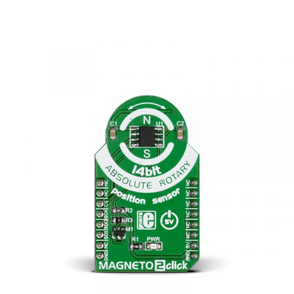
Magneto 2 click is a mikroBUS™ add-on board with Melexis's MLX90316 monolithic rotary position sensor.
Sensing flux density with the IC surface of the MLX90316 allows the click to decode the absolute rotary (angular) position from 0 to 360 degrees.
In combination with the correct library, the magnetic flux density of a small magnet (diametral magnetisation) rotating above the IC can be measured in a non-contacting way.
Features and usage notes
- Tri⊗is® Hall Technology
- 40 bit ID number
- Single Die - SO8 or Dual Die (Full Redundant) - TSSOP16, RoHS Compliant
- Absolute Rotary Position Sensor IC
- Changeable main frequency for DSP chip (7MHz or 20 MHz master clock)
- Hysteresis Filter
- FIR and IIR filters for higher output accuracy
- Programmable Linear Transfer Characteristic
- SPI interface
- 5V Power Supply
Programming
This code initialises UART and SPI, reads data from the Magneto 2 click, and, if the readings are successful, prints it out on the UART
 1 void main() {
2     char txt[20];
3     uint8_t check = 0;
4     float angle = 0.0;
5     UART1_Init_Advanced( 9600,  _UART_8_BIT_DATA,
6                          _UART_NOPARITY,
7                          _UART_ONE_STOPBIT,
8                          &_GPIO_MODULE_USART1_PA9_10 );
9     Delay_ms(300);
10
11     UART1_Write_Text("Uart initializedrn");
12     GPIO_Digital_Output( &GPIOD_BASE, _GPIO_PINMASK_13 ); // set CS pin as output
13
14     // Initialize SPI
15
16     SPI3_Init_Advanced(_SPI_FPCLK_DIV64, _SPI_MASTER   |
17                        _SPI_8_BIT | _SPI_CLK_IDLE_LOW  |
18                        _SPI_SECOND_CLK_EDGE_TRANSITION |
19                        _SPI_MSB_FIRST                  |
20                        _SPI_SS_DISABLE                 |
21                        _SPI_SSM_ENABLE                 |
22                        _SPI_SSI_1, &_GPIO_MODULE_SPI3_PC10_11_12);
23     SPI_Set_Active(&SPI3_Read, &SPI3_Write);      // Sets the SPI1 module active
24
25
26     while (1)
27     {
28         check = read_mlx();
29         if ( check == 0)                          // if read was successful, print success and angle
30         {
31             Uart1_Write_Text("Success rn");
32             angle = (float) mlx.angle;
33             angle /= 45.5;
34             floattostr(angle,txt);
35             Uart1_Write_Text(txt);
36             Uart1_Write_Text("rn");
37         }
38         else                                     // else print fail
39             Uart1_Write_Text("Fail rn");
40
41         Delay_ms(400);                // Wait 400ms
42     }
43 }
Code example that demonstrates the usage of Magneto 2 click with MikroElektronika hardware, written for mikroC for ARM is available on Libstock.


