
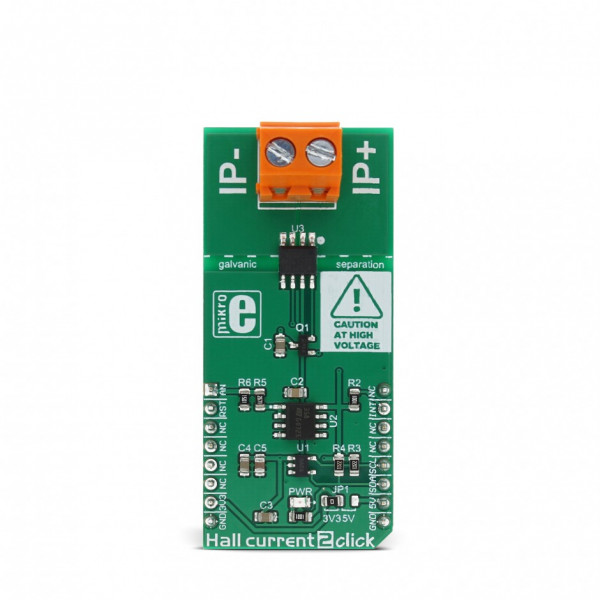
Hall current 2 click


Prices incl. VAT plus shipping costs
Ready to ship today,
Delivery time appr. 1-3 workdays
- Order number: MIKROE-2987
- Manufacturer product ID: MIKROE-2987
Hall current 2 click is a very accurate current measurement Click board™, which relies on the Hall effect. Its most distinctive feature is a very low series resistance of only 1.2m?, making this device a nearly-perfect ampere meter. The maximum current which can be measured with the Hall current 2 ranges from -12A to +12A, with optimized precision. The measurement is thermally compensated and conditioned by the integrated sections of the hall sensor IC. The result is available via the I2C interface of the high precision, 12 bit AD converter, as well as in the analog form, from the analog pin of the microBUS™, directly from the Hall effect current sensor IC. This click board does not require any current sensing resistors.
Featuring a reasonably high current range that can be measured, extremely low series resistance, clever design which includes measurement reading in both analog and digital format, and very advanced Hall effect current sensor IC, especially designed for the current measurement applications, which can withstand overcurrent conditions up to five times of the nominal measuring current range, this Click board™ can be used for a wide range of measuring and monitoring applications in audio applications, telecommunication applications, white goods applications, and basically in every application which requires current measurement or monitoring, working in the range of less than 100 V.
How does it work?
Hall current 2 utilizes the ACS711, a Hall effect linear current sensor with overcurrent fault output for less than 100 V Isolation Applications, from Allegro Microsystems. This sensor utilizes the Hall effect phenomena to measure the current passing through the internally fused input pins of the IC. This allows the series resistance to stay very low. Current flow through the input rails of the IC generates a magnetic field, causing the Hall effect on the current flow through the integrated sensor. The resulting voltage is further conditioned and offset by the internal sections of the ACS711 IC, and after the conditioning, it appears at the output of the VIOUT pin.
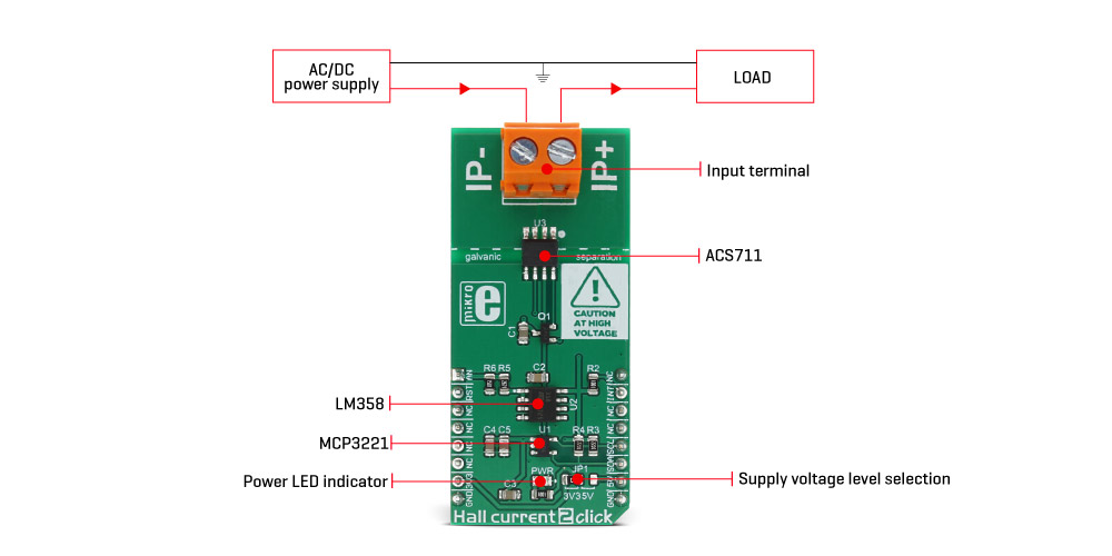
The output voltage changes linearly with the input current, in steps of 110mV/A. To allow conversion via the external ADC, the output voltage is passed through the buffering circuit, comprised of the LM358 - a low noise operational amplifier in a unity gain configuration. The output of this buffer network is connected to the AN pin of the mikroBUS™ allowing an external AD conversion, or utilizing the output voltage in some other way. The response time of the output voltage is very short - in a magnitude of microseconds.
The output voltage is also routed to the MCP3221, a 12 Bit SAR type ADC with the I2C interface, from Microchip. This ADC is used in several different Click board™ designs, as it yields accurate conversions, it requires a low count of external components, and has a reasonably good signal to noise ratio (SNR). It can achieve up to 22.3ksps, which allows good measurement resolution for the most purposes. After the ACS711 output voltage has been converted to a digital value, it can be read via the I2C bus of the MCP3221 ADC. The I2C bus lines are routed to the respective I2C lines of the mikroBUS™ (SCL - clock; SDA - data). The provided library contains functions for simplified reading of the conversion values.
The FAULT pin indicates an overcurrent condition. If the measured current exceeds the specified range, this pin will be latched to a LOW logic level. This pin has a very fast response of only 1.3 µs, allowing it to be used a part of the overcurrent protection circuit. Naturally, it can be used as the interrupt pin, triggering an interrupt request on a host MCU. For this reason, it is routed to the INT pin of the mikroBUS™.
However, once latched, the ACS711 IC requires power cycling for the FAULT pin to be released. This can be done by pulling the RST pin of the mikroBUS™ to a HIGH logic level. This will cut the power through the PNP BJT. Pulling the RST pin to a LOW logic level will allow current flow through the BJT once again, and thus the ACS711 will release the FAULT pin. For the normal operation, RST pin should stay at the LOW logic level.
The onboard SMD jumper allows selection between 3.3V and 5V. This allows both 3.3V and 5V MCUs to communicate with the Hall current 2 click.
The ACS711 IC offers a galvanic isolation for up to 100V. A care should be taken when operating with high voltages, not to touch the Click board™.
Specifications
| Type | Current |
| Applications | Audio applications, telecommunication applications, white goods applications, and every application which requires current measurement or monitoring. |
| On-board modules | ACS711 Hall-effect linear current sensor with overcurrent fault output |
| Key Features | Very low series resistance, which makes this sensor an ideal ammeter. Analog and digital reading of the measurement data, wide current input range, great accuracy, low count of external components |
| Interface | Analog,I2C |
| Input Voltage | 3.3V or 5V |
| Click board size | L (57.15 x 25.4 mm) |
Pinout diagram
This table shows how the pinout on Hall current 2 click corresponds to the pinout on the mikroBUS™ socket (the latter shown in the two middle columns).
| Notes | Pin | Pin | Notes | ||||
|---|---|---|---|---|---|---|---|
| Analog reading | AN | 1 | AN | PWM | 16 | NC | |
| Reset / INT unlatch | RST | 2 | RST | INT | 15 | INT | Interrupt |
| NC | 3 | CS | RX | 14 | NC | ||
| NC | 4 | SCK | TX | 13 | NC | ||
| NC | 5 | MISO | SCL | 12 | SCL | I2C Clock | |
| NC | 6 | MOSI | SDA | 11 | SDA | I2C Data | |
| Power Supply | +3V3 | 7 | 3.3V | 5V | 10 | +5V | Power Supply |
| Ground | GND | 8 | GND | GND | 9 | GND | Ground |
Hall current 2 click maximum ratings
| Description | Min | Typ | Max | Unit |
|---|---|---|---|---|
| Primary conductor resistance | - | 1.2 | - | m? |
| Optimized accuracy measurement range | -12 | - | +12 | A |
| Sensitivity | - | 110 | - | mV/A |
| Allowed voltage across the device (between pins 1-4 and pins 5-8) | - | - | 100 | V |
Onboard settings and indicators
| Label | Name | Default | Description |
|---|---|---|---|
| JP1 | JP1 | Left | Power Supply Voltage Selection: Left position 3V3, right position 5V |
| LD1 | PWR | PWR indication LED |
Software support
We provide a library for Hall current 2 click on our Libstock page, as well as a demo application (example), developed using MikroElektronika compilers and mikroSDK. The provided click library is mikroSDK standard compliant. The demo application can run on all the main MikroElektronika development boards.
Library Description
This library provides basic functionality for reading the current value and controlling the Click board™.
Key functions:
void hallcurrent2_reset(); - Function for reseting the click board sensor.
int16_t hallcurrent2_getData(); - Function that returns the 12bit digital value.
int16_t hallcurrent2_getCurrent(); - Function that returns the current value.
Examples Description
The application is composed of three sections:
- System Initialization - Initializes I2C module and INT pin as INPUT and RST pin as OUTPUT.
- Application Initialization - Initializes Driver init and reset chip.
- Application Task - (code snippet) - Reads current and logs on USB UART every 1 second.
It was tested with 1V voltage at the input and with a load of 1 - 2A.
void applicationTask()
{
CurrentData = hallcurrent2_getCurrent();
IntToStr(CurrentData, text);
mikrobus_logWrite("--- Current :", _LOG_TEXT);
mikrobus_logWrite(text, _LOG_TEXT);
mikrobus_logWrite(" mA", _LOG_LINE);
Delay_ms( 1000 );
}
The full application code, and ready to use projects can be found on our Libstock page.
Other mikroE Libraries used in the example:
- UART Library
- Conversions Library
- C_String Library
- I2C Library
Additional notes and information
Depending on the development board you are using, you may need USB UART click, USB UART 2 click or RS232 click to connect to your PC, for development systems with no UART to USB interface available on the board. The terminal available in all MikroElektronika compilers, or any other terminal application of your choice, can be used to read the message.
mikroSDK
This Click board™ is supported with mikroSDK - MikroElektronika Software Development Kit. To ensure proper operation of mikroSDK compliant Click board™ demo applications, mikroSDK should be downloaded from the LibStock and installed for the compiler you are using.