
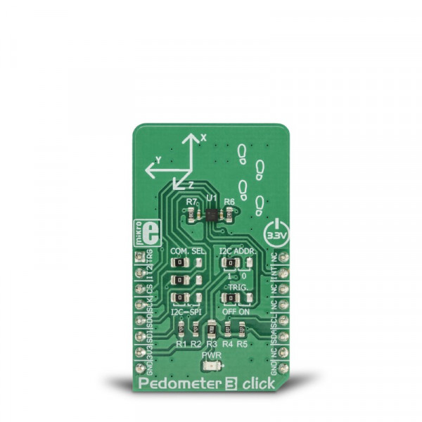
Pedometer 3 Click


- Order number: MIKROE-3259
- Manufacturer product ID: MIKROE-3259
The micro-electromechanical sensor (MEMS) is coupled with a very advanced ASIC, which offers many advanced features, such as the 2048-byte FIFO buffer, pedometer algorithms, tap, and double tap sensing algorithms, free fall algorithms, tilt single/double pole IIR filtering, and more.
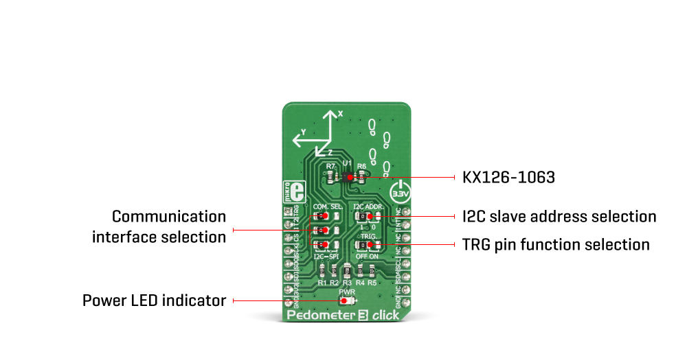
This Click board™ features the advanced KX126-1063 sensor based on the advanced application-specific IC (ASIC), coupled with the reliable and accurate micro-electromechanical sensor (MEMS) manufacturing technology.
How does it work?
Pedometer 3 click is equipped with the KX126-1063, ±2g / ±4g / ±8g / ±16g tri-axis digital accelerometer, by Kionix. This sensor utilizes an advanced acceleration sensing method, based on the differential capacitance. The integrated MEMS, produced with the proprietary Kionix technology, is composed of two plates. One is fixed to the substrate, while the other can move freely along a single axis. The acceleration causes the change in the capacitance between these plates, which is then processed by an integrated ASIC. The ASIC incorporates a capacitance-to-voltage amplifier which converts the differential capacitance of the MEMS sensor into an analog voltage, used as the input for the low-noise A/D converter (ADC). The integrated ASIC also contains the logic section used to set all the operational parameters of the KX126-1063, such as the data rate, filter settings, interrupts, ADC resolution, and other settings. The ASIC also incorporates an OTP memory that contains the calibration parameters and other device-specific settings used on each power-on reset (POR) cycle.
The ADC can be operated with the resolution of 8 or 16 bits. This allows power consumption to be managed, as the lower resolution typically allows less power consumption. The power consumption is also affected by the output data rate value (ODR). The ODR value can be set for each mode and is set by different bits located in the respective configuration registers.
As previously mentioned, the KX126-1063 IC features a range of different detection algorithms, which are used to detect a range of movement and acceleration events. The pedometer functionality is one of these features. In the datasheet, a term engine is used. The pedometer engine can be disabled or enabled, it can have the signal filtering conditioning applied to it (so that the acceleration offset is removed, and the peak detection is improved), it can use a specific acceleration range from ±2g to ±16g, it can set its output data rate register to a specific value, it can have the step count overflow reported as the interrupt on one of the physical pins (INT1, and INT2 pins of the IC, routed to the mikroBUS™ INT and RST pins, respectively), step increment event can also be directed to trigger an interrupt on one of the INT pins. The step detection parameters of the pedometer engine itself can be configured by the user. There are ten pedometer control registers (PED_CNTL1 to PED_CNTL10) that cover various aspects of the pedometer engine, in addition to general configuration registers which are common to all engines of the KX126-1063 IC. These registers affect the step detection sensitivity, the number of steps discarded before the actual counting begins, the scaling factor, etc. The datasheet of the KX126-1063 IC offers a detailed explanation of each register and its function. However, the Click board™ comes with the mikroSDK compatible library which contains simplified functions, that allow simple setup of the KX126-1063 sensor IC and rapid application development.
The advanced interrupt engine allows both the interrupt pins INT1 and INT2 to be configured by the user. They can be used to trigger an interrupt on the host MCU, using a wide range of sources, including sample buffer events, various engine-specific events, general purpose interrupts (such as wake-up, data ready, and similar), etc. Having two independent interrupt pins is a great solution for optimizing the firmware of the host controller, as the register polling can be reduced greatly, saving valuable MCU processing resources.
Another feature of the KX126-1063 IC is its advanced sample buffer, which can store up to 2048 bytes of data. It can be operated in four different modes, including FIFO, FILO, Stream, and Trigger modes. Each mode applies a different set of rules when filling in the sample buffer, and when the watermark level is reached (a user-configurable threshold). The TRIG pin used for an external buffer control is routed to the mikroBUS™ AN pin labeled as TRG. This pin is used when the sample buffer is operated in Trigger mode: a high logic state on this pin will retain all the samples in the buffer up to the current position (not discarding them anymore when the threshold level is reached), continuing to fill the buffer until its full. When this option is not used, the TRIG pin should be grounded, which is done by positioning the SMD jumper labeled as TRIG, to OFF position (the factory default for the Click board™). Again, more detailed information about the advanced sample buffer can be found in the KX126-1063 IC datasheet.
Each KX126-1063 device is factory calibrated, and its calibration parameters are stored in the one-time programmable memory (OTP). These parameters include the gain corrections and offset calibration. After each POR cycle, these calibration values are automatically applied, reducing the output error. Along with the used MEMS differential sensing technology, this reduces the measurement error to a virtually unmeasurable value. A built-in self-test function allows reliable operation of the Pedometer 3 click.
Pedometer 3 click can use both SPI and I2C interfaces. A group of SMD jumpers labeled as COM SEL is used to select either of the communication interfaces. Please note that all the COM SEL jumpers must be positioned at the same setting, else the communication with the Click board™ will not be possible. When operated in I2C mode, the slave address of the device can be changed by switching the position of the SMD jumper labeled as I2C ADD. The Click board™ should be interfaced only with MCUs that use the communication voltage level of 3.3V.
Specifications
| Type | Motion |
| Applications | It can be used for pedometer applications development, display orientation, HID applications, drop detection applications (for warranty logging), and similar applications that can utilize the advanced motion and acceleration features the Pedometer 3 click can offer. |
| On-board modules | KX126-1063, ±2g / ±4g / ±8g / ±16g tri-axis digital accelerometer, by Kionix |
| Key Features | Advanced event detection engines, proprietary Kionix MEMS technology, data conditioning and processing allows reliable operation of the detection engines, offers both I2C and SPI interface, an advanced sample buffer and interrupt engine with two programmable pins simplify firmware development. |
| Interface | I2C,SPI |
| Input Voltage | 3.3V |
| Click board size | M (42.9 x 25.4 mm) |
Pinout diagram
This table shows how the pinout on Pedometer 3 Click corresponds to the pinout on the mikroBUS™ socket (the latter shown in the two middle columns).
| Notes | Pin | Pin | Notes | ||||
|---|---|---|---|---|---|---|---|
| Sample buffer CTRL | TRG | 1 | AN | PWM | 16 | NC | |
| Interrupt #2 | IT2 | 2 | RST | INT | 15 | INT | Interrupt #1 |
| SPI Chip Select | CS | 3 | CS | RX | 14 | NC | |
| SPI Clock | SCK | 4 | SCK | TX | 13 | NC | |
| SPI Data OUT | SDO | 5 | MISO | SCL | 12 | SCL | I2C Clock |
| SPI Data IN | SDI | 6 | MOSI | SDA | 11 | SDA | I2C Data |
| Power supply | 3V3 | 7 | 3.3V | 5V | 10 | NC | |
| Ground | GND | 8 | GND | GND | 9 | GND | Ground |
Onboard settings and indicators
| Label | Name | Default | Description |
|---|---|---|---|
| PWR | PWR | - | Power LED indicator |
| JP1 | TRIG | Left | Trigger pin function select: left position - disabled, right position - enabled |
| JP2 | I2C ADDR | Left | I2C slave address selection: left position - LSB = 1, right position - LSB = 0; |
| JP3-JP5 | COM SEL | Left | Communication interface selection: left position I2C, right position SPI |
Software support
We provide a library for the Pedometer 3 click on our LibStock page, as well as a demo application (example), developed using MikroElektronika compilers. The demo can run on all the main MikroElektronika development boards.
Library Description
The library initializes and defines the I2C or SPI bus driver and drivers that offer a choice for writing data in the register and reads data from register. The library includes the function for reading Accel X/Y/Z axis data, the function for reading pedometer stem counter, the function for detect Tilt and Tap. The user also has the functions for configuration device functions for reads interrupt states.
Key functions:
void pedometer3_getAccelAxis(int16_t *x_axis, int16_t *y_axis, int16_t *z_axis)- Functions for reading Accel axis data
uint16_t pedometer3_getPedometerStepCounter()- Functions for getting pedometer step counter
void pedometer3_getTiltPosition(uint8_t *current_pos, uint8_t *previous_pos)- Functions for getting Tilt current and previous position
void pedometer3_getTapDetection(uint8_t *tap)- Functions for getting Tap detection
Examples description
The application is composed of the three sections :
- System Initialization - Initializes I2C module and sets INT pin, AN pin and RST pin as INPUT and CS pin as OUTPUT
- Application Initialization - Initialization driver init and start configuration chip for measurement
- Application Task - (code snippet) - Reads Accel and High Pass Accel X/Y/Z axis and detect Tilt Position. All data logs on the USB UART every 500 ms.
Note: The start configuration chip is required at the beginning of each program so that the chip wakes up and prepares for operation and measurement. What is included and set in the start-up function can be viewed in the help file.
void applicationTask()
{
pedometer3_getAccelAxis( &X_accelAxis, &Y_accelAxis, &Z_accelAxis );
pedometer3_getHighPassAccelAxis( &X_hpAxis, &Y_hpAxis, &Z_hpAxis );
pedStep += pedometer3_getPedometerStepCounter();
mikrobus_logWrite("|___________ Pedometer 3 click _____________|", _LOG_LINE );
mikrobus_logWrite("|  Data    |  X axis  |  Y axis  |  Z axis  |", _LOG_LINE );
mikrobus_logWrite("|  Accel   |", _LOG_TEXT );
IntToStr(X_accelAxis, demoText);
mikrobus_logWrite(demoText, _LOG_TEXT);
mikrobus_logWrite("    |", _LOG_TEXT);
IntToStr(Y_accelAxis, demoText);
mikrobus_logWrite(demoText, _LOG_TEXT);
mikrobus_logWrite("    |", _LOG_TEXT);
IntToStr(Z_accelAxis, demoText);
mikrobus_logWrite(demoText, _LOG_TEXT);
mikrobus_logWrite("    |", _LOG_LINE);
mikrobus_logWrite("| HP Accel |", _LOG_TEXT );
IntToStr(X_hpAxis, demoText);
mikrobus_logWrite(demoText, _LOG_TEXT);
mikrobus_logWrite("    |", _LOG_TEXT);
IntToStr(Y_hpAxis, demoText);
mikrobus_logWrite(demoText, _LOG_TEXT);
mikrobus_logWrite("    |", _LOG_TEXT);
IntToStr(Z_hpAxis, demoText);
mikrobus_logWrite(demoText, _LOG_TEXT);
mikrobus_logWrite("    |", _LOG_LINE);
mikrobus_logWrite("|___________________________________________|", _LOG_LINE );
mikrobus_logWrite("| Pedometer step counter :", _LOG_TEXT );
IntToStr(pedStep, demoText);
mikrobus_logWrite(demoText, _LOG_TEXT);
mikrobus_logWrite("            |", _LOG_LINE);
mikrobus_logWrite("|___________________________________________|", _LOG_LINE );
pedometer3_getTiltPosition(&CurrentTiltPosition, &PreviousTiltPosition);
mikrobus_logWrite("| Current Tilt Position  :", _LOG_TEXT );
switch(CurrentTiltPosition)
{
case 1:
{
mikrobus_logWrite("- LEFT            |", _LOG_LINE );
break;
}
case 2:
{
mikrobus_logWrite("- RIGHT           |", _LOG_LINE );
break;
}
case 3:
{
mikrobus_logWrite("- DOWN            |", _LOG_LINE );
break;
}
case 4:
{
mikrobus_logWrite("- UP              |", _LOG_LINE );
break;
}
case 5:
{
mikrobus_logWrite("- FACE DOWN       |", _LOG_LINE );
break;
}
case 6:
{
mikrobus_logWrite("- FACE UP         |", _LOG_LINE );
break;
}
}
mikrobus_logWrite("|___________________________________________|", _LOG_LINE );
mikrobus_logWrite("  ", _LOG_LINE);
Delay_ms( 400 );
}
The full application code, and ready to use projects can be found on our LibStock page.
Other mikroE Libraries used in the example:
I2C
Additional notes and information
Depending on the development board you are using, you may need USB UART click, USB UART 2 click or RS232 click to connect to your PC, for development systems with no UART to USB interface available on the board. The terminal available in all MikroElektronika compilers, or any other terminal application of your choice, can be used to read the message.