
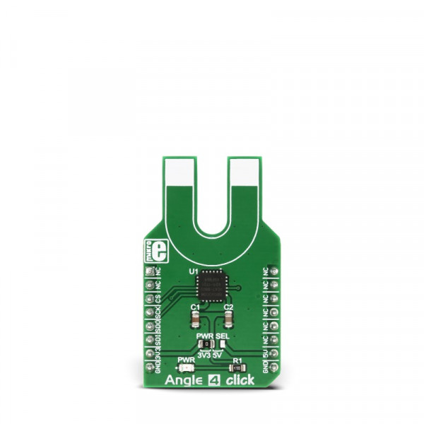
Angle 4 click


- Order number: MIKROE-3130
- Manufacturer product ID: MIKROE-3130
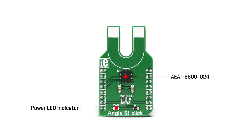
The AEAT-8800-Q24 IC utilizes integrated Hall sensor elements, accompanied by very sophisticated circuits for processing analog and digital signals, resulting in a very robust and precise rotary sensing interface. This makes Angle 4 click an ideal solution for a wide variety of contactless angle measurement applications, such as the acquisition of position and rotation for various BLDC or stepper motors, mechanical potentiometer replacement, for building various HMI platforms, in robotics, and similar applications.
How does it work?
As already mentioned, Angle 4 click uses the AEAT-8800-Q24, an integrated 10 to 16-bit programmable angular magnetic encoder, by Broadcom. This sensor relies on integrated Hall elements and complex analog front end and digital signal processing, in order to provide absolute angular position over the industry standard SPI interface. The user has the ability to programmatically set the zero position, direction, hysteresis, and the resolution. This allows the Click board™ to be tailored according to needs for a range of different applications.
The possibility to sense the rotational angle of a diametrically magnetized object parallel with the Click board™ surface, gives an opportunity to develop both contactless rotational and positional measurement applications, as well as the human-machine interfaces (HMI), such as the rotary encoders, digital potentiometers, and similar. The calibration is simple, and the AEAT-8800-Q24 datasheet provides a detailed explanation how to calibrate the device by using a diametrically magnetized object (i.e. a magnetic disc), with its axis aligned to the center of the sensor. For the best results, the magnet properties should be according to specifications in the datasheet. Once calibrated, it can be permanently used, with no additional recalibrations.
The AEAT-8800-Q24 uses the non-volatile one-time programming memory during the operation. It contains registers with the calibration values, zero offsets, resolution and so on. All the OTP locations have their shadow locations, which allow writing, but only when the unlock command is issued (writing 0xAB to the location 0x10). However, the values will be lost after the power cycle and will be rewritten with the values contained in the OTP memory.
The library provided with Angle 4 click offers several simple and useful functions, among which is the angle4_calibration function, which will automatically program the direction and the resolution parameters to the OTP memory, passed as argumetns to this function. However, the OTP memory will not be permanently written, unless appropriate programming voltage is applied to the VDDP pin. Since the OTP memory can be programmed only once, a thorough understanding of the OTP programming process is required. More information about the OTP programming process can be found in the AEAT-8800-Q24 datasheet.
The Click board™ contains an SMD jumper, labeled as PWR SEL, which can be used to set the operating voltage of the click board to either 3.3V or to 5V. This allows a wide range of different MCUs to be interfaced with the Click board™, operating both at 3.3V and 5V.
Specifications
| Type | Magnetic |
| Applications | It is an ideal solution for a wide variety of contactless angle measurement applications, such as the acquisition of position and rotation for various BLDC or stepper motors, mechanical potentiometer replacement, for building various HMI platforms, in robotics, and similar applications |
| On-board modules | AEAT-800-Q24, an integrated 10 to 16-bit programmable angular magnetic encoder, by Broadcom |
| Key Features | Accurate sensing of the magnetic angle, providing absolute positional readings over the SPI, good linearity and low error margin over 360?, programmable working parameters, OTP memory for permanent working parameters storage |
| Interface | SPI |
| Input Voltage | 3.3V or 5V |
| Click board size | M (42.9 x 25.4 mm) |
Pinout diagram
This table shows how the pinout on Angle 4 click corresponds to the pinout on the mikroBUS™ socket (the latter shown in the two middle columns).
| Notes | Pin | Pin | Notes | ||||
|---|---|---|---|---|---|---|---|
| NC | 1 | AN | PWM | 16 | NC | ||
| NC | 2 | RST | INT | 15 | NC | ||
| SPI Chip Select | CS | 3 | CS | RX | 14 | NC | |
| SPI Clock | SCK | 4 | SCK | TX | 13 | NC | |
| SPI Data OUT | SDO | 5 | MISO | SCL | 12 | NC | |
| SPI Data IN | SDI | 6 | MOSI | SDA | 11 | NC | |
| Power supply | 3.3V | 7 | 3.3V | 5V | 10 | 5V | Power supply |
| Ground | GND | 8 | GND | GND | 9 | GND | Ground |
Onboard settings and indicators
| Label | Name | Default | Description |
|---|---|---|---|
| LD1 | PWR | - | Power LED indicator |
| JP1 | PWR SEL | Left | Power supply voltage selection: left position 3.3V, right position 5V |
Software support
We provide a library for the Angle4 Click on our LibStock page, as well as a demo application (example), developed using MikroElektronika compilers. The demo can run on all the main MikroElektronika development boards.
Library Description
Library initializes and defines SPI bus driver and driver functions which offer a choice to write data in registers and to read data from registers. Library also offers a choice to sets absolute resolution read data and sets the direction. A user has an angle-reading function, a function for starting the measurement, and starting the chip calibration that is necessary for operation.
Key functions:
vuint8_t angle4_getNewAngle(uint16_t *dataOut)- Functions for read Anglevoid angle4_startMesuremenet()- Functions for start measurementvoid angle4_calibration(uint8_t dir, uint8_t data_resolution)- Functions for calibration chip
Example description
The application is composed of three sections:
- System Initialization - Initializes SPI module and set CS pin as OUTPUT
- Application Initialization - Driver initialization, standard configurations, and start measurement
- Application Task - (code snippet) - Reads Angle in degrees and logs data to USBUART every 200 ms.
void applicationTask()
{
angle4_getNewAngle(&Angle);
IntToStr(Angle, demoText);
mikrobus_logWrite(" Angle : ", _LOG_TEXT);
mikrobus_logWrite(demoText, _LOG_TEXT );
mikrobus_logWrite(" deg", _LOG_LINE);
Delay_ms( 200 );
}
The full application code, and ready to use projects can be found on our Libstock page.
Other MikroElektronika libraries used in the example:
- SPI
- Conversions
Additional notes and information
Depending on the development board you are using, you may need USB UART click, USB UART 2 click or RS232 click to connect to your PC, for development systems with no UART to USB interface available on the board. The terminal available in all MikroElektronika compilers, or any other terminal application of your choice, can be used to read the message.
mikroSDK
This click board is supported with mikroSDK - MikroElektronika Software Development Kit. To ensure proper operation of mikroSDK compliant click board demo applications, mikroSDK should be downloaded from the LibStock and installed for the compiler you are using.