
WiFi ESP click


- Order number: MIKROE-2542
- Manufacturer product ID: MIKROE-2542
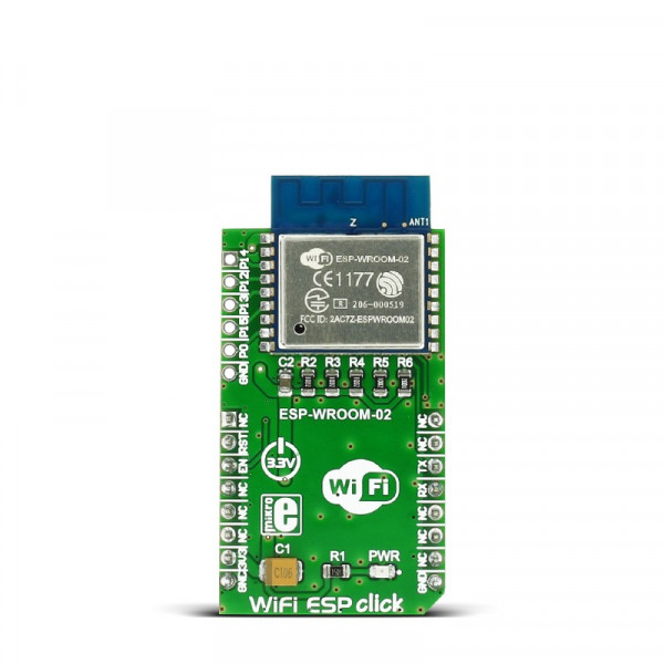
WiFi ESP click carries the ESP-WROOM-02 module that integrates ESP8266EX. The click is designed to run on a 3.3V power supply. It communicates with the target microcontroller over UART interface and the following pins on the mikroBUS™ line: RST, CS.
Access point and WiFi client mode
WiFi ESP click can function in both AP (Access Point) WiFi mode, as well as in WiFi client mode. The click brings easy implementation and usage.
The module supports the following network protocols: IPv4/TCP/UDP/HTTP/FTP. Thanks to this the click can operate as a client device requesting a file from a file server device (FTP - file transfer protocol) in local network systems, or request a web page via internet (IP/TCP/HTTP). It can also be used as a small web server, for example a wireless weather station prototype, etc.
Station mode is default when the click is in WiFi client mode.
ESP-WROOM-02 module features
ESP-WROOM-02 carries ESP8266EX highly integrated Wi-Fi SoC solution to meet the continuous demands for efficient power usage, compact design and reliable performance in the industry.
Besides the Wi-Fi functionalities, ESP8266EX integrates an enhanced version of Tensilica’s L106 Diamond series 32-bit processor and on-chip SRAM. As well as antenna switches, RF balun, power amplifier, low noise receiver amplifier, filters and power management modules.
With the complete and self-contained Wi-Fi networking capabilities, it can perform as either a standalone application (WROOM module itself) or the slave to an MCU host which is the primary intention of the click board as a whole. So, this click board is applied to any microcontroller design as a Wi-Fi adaptor through UART interface (RX,TX lines on mikroBUS pin socket).
For more information see the datasheet.
Advanced usage
There are additional pad headers onboard (HSPI/GPIO interface of the module) for advanced usage.
For more information see the Documentation tab.
Specifications
| Type | Wi-Fi |
| Applications | Create smart appliances, home automation systems, wireless data loggers, etc |
| MCU | ESP-WROOM-02 |
| Key Features | Protocols: IPv4, TCP/UDP/HTTP/FTP, 802.11 b/g/n standard, UART interface, 3.3V power supply |
| Key Benefits | The click can function in both AP mode and WiFi client mode |
| Interface | GPIO,UART |
| Input Voltage | 3.3V |
| Compatibility | mikroBUS |
| Click board size | M (42.9 x 25.4 mm) |
Pinout diagram
This table shows how the pinout on WiFi ESP click corresponds to the pinout on the mikroBUS™ socket (the latter shown in the two middle columns).
| Notes | Pin | Pin | Notes | ||||
|---|---|---|---|---|---|---|---|
| NC | 1 | AN | PWM | 16 | NC | ||
| HW Reset | RST | 2 | RST | INT | 15 | NC | |
| Chip enable (active high) | EN | 3 | CS | TX | 14 | TX | UART0_TXD / Transmit end in UART download (program) mode |
| NC | 4 | SCK | RX | 13 | RX | UART0_RXD / Receive end in UART download (program) mode | |
| NC | 5 | MISO | SCL | 12 | NC | ||
| NC | 6 | MOSI | SDA | 11 | NC | ||
| Power supply | +3.3V | 7 | 3.3V | 5V | 10 | NC | |
| Ground | GND | 8 | GND | GND | 9 | GND | Ground |
Additional pins
| Name | I/O | Description |
|---|---|---|
| CLK | IO | HSPI_CLK / GPIO14 |
| SDO | IO | HSPI_MISO / GPIO12 |
| SDI | IO | HSPI_MOSI / GPIO13 |
| CS | IO | HSPI_CS / GPIO15 |
| IO0 | IO | GPIO0 (UART download mode - pull down, Flash boot - pull up) |
| GND | GND |
Buttons and LEDs
| Designator | Name | Type (LED, BUTTON…) | Description |
|---|---|---|---|
| LD1 | PWR | LED | Power Supply ON |
Programming
Code examples for WiFi ESP click, written for MikroElektronika hardware and compilers are available on Libstock.
Code snippet
This code snippet configures GPIO ports, initializes the display and prepares the WiFi module. In an endless loop, LED is enabled or disabled by a button, and that information is then sent to the server.
01 void main() {
02
03   // Initialize variables
04   length = 0;
05   state = 0;
06   response_rcvd = 0;
07   responseID = 0;
08   response = 0;
09   i = 0;
10
11   // GPIO Direction
12   GPIO_Digital_Input( &GPIOA_IDR, _GPIO_PINMASK_4 );
13   GPIO_Digital_Output( &GPIOD_BASE, _GPIO_PINMASK_13 );
14   GPIO_Digital_Output( &GPIOC_BASE, _GPIO_PINMASK_2 );
15   GPIO_Digital_Output( &GPIOA_ODR, _GPIO_PINMASK_0 );
16
17   // UART Initialization
18   UART3_Init_Advanced( 115200, _UART_8_BIT_DATA,
19                              _UART_NOPARITY,
20                              _UART_ONE_STOPBIT,
21                              &_GPIO_MODULE_USART3_PD89);
22
23   // Enable Interrupts
24   RXNEIE_USART3_CR1_bit = 1;
25   NVIC_IntEnable( IVT_INT_USART3 );
26   EnableInterrupts();
27
28   display_init();
29
30   // Initialize WiFI module
31   WiFi_Init();
32
33   // Setting WiFi Mode - SoftAP + station mode
34   WiFI_Configure();
35
36   state = 100;
37   i = 0;
38
39   TFT_Write_Text("Please connect to your STAIP...", 50, 100);
40   Delay_ms(20000);
41   WiFi3_Send();
42   TFT_Write_Text("Entering button toggling loop.", 50, 150);
43
44   LED_switching = 1;
45
46     while( 1 )
47     {
48       // detect logical one on PA4 pin
49       if (Button(&GPIOA_IDR, 4, 1, 1))
50       {
51        oldstate_A4 = 1;
52       }
53       // detect logical one-to-zero transition on PA4 pin
54       if (oldstate_A4 && Button(&GPIOA_IDR, 4, 1, 0))
55       {
56         if ( !strcmp(txt_state_A0, "OFF" ))
57         {
58           strncpy( txt_state_A0, "ON ", 8 );
59           GPIOA_ODR.B0 = 1;
60         }
61         else
62         {
63           strncpy( txt_state_A0, "OFF", 8 );
64           GPIOA_ODR.B0 = 0;
65         }
66         oldstate_A4 = 0;
67         A0_change = true;
68         WiFi3_Send();
69       }
70     }
71 }