
GSM/GNSS click


Prices incl. VAT plus shipping costs
Ready to ship today,
Delivery time appr. 1-3 workdays
- Order number: MIKROE-2439
- Manufacturer product ID: MIKROE-2439
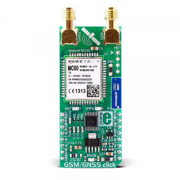
GSM/GNSS click combines GPS/GLONASS location tracking with GSM module capability for mobile communication. The click features Quectel’s MC60 quad-band module. GSM/GNSS click runs on either 3.3V or 5V power supply and communicates with the target MCU over UART interface, and the following mikroBUS™ pins: AN, RST, PWM, INT.
When connected to a GPS antenna, it can receive GPS coordinates, time, and other information from orbiting satellites. The click can be used for all GSM functions — calls, messages (SMS, MMS), mobile internet.
GSM/GNSS click has an onboard MicroSD card socket, micro SIM card socket, a Bluetooth antenna (the MC60 module supports Bluetooth 3.0) and additional pins for connecting speakers and a microphone.
Quectel’s MC60 quad-band module
MC60 is a quad-band full-featured GSM/GPRS module using LCC castellation package. With an extensive set of internet protocols (TCP, UDP, PPP, FTP, HTTP and SSL*), it has integrated GNSS technology for satellite navigation.
The module can balance between positioning accuracy and power consumption according to the environmental and motion conditions. The typical power consumption is around 2.8mA.
Positioning — EASY™ technology
EASY™ is the abbreviation of Embedded Assist System for quick positioning. With EASY™ technology, MC60’s GNSS engine can automatically calculate and predict orbits using the ephemeris data (up to 3 days) when the power is on, and then save that information into the memory.
The GNSS engine can use this information for later positioning, if there is not enough information from the satellites.
GPS and GLONASS
GNSS stands for Global Navigation Satellite System, an umbrella term that describes both the United States GPS and the Russian GLONASS global positioning systems. GLONASS is an acronym for Globalnaya Navigatsionnaya Sputnikovaya Sistema (Global Navigation Satellite System).
GPS currently has 33 satellites in orbit, and GLONASS has 24. This two-constellation system is particularly suitable for urban areas with high-rise buildings and complex environments.
GLONASS is suited for usage in high latitudes (north or south), where getting a GPS signal can be difficult.
Application
Asset tracking, for navigation devices based on GPS and GLONASS, road navigation devices, public transport, wearable devices, etc.
Specifications
| Type | GPS,GSM |
| Applications | Asset tracking, for navigation devices based on GPS and GLONASS, road navigation devices, public transport, wearable devices, etc. |
| Key Features | MC60 quad-band module, GPS/GNSS location tracking, UART interface, 3.3V or 5V power supply |
| Key Benefits | GPS, GNSS, GSM, and Bluetooth in one click |
| Interface | UART,GPIO |
| Input Voltage | 3.3V or 5V |
| Compatibility | mikroBUS |
| Click board size | L (57.15 x 25.4 mm) |
Pinout diagram
This table shows how the pinout on GSM/GNSS click corresponds to the pinout on the mikroBUS™ socket (the latter shown in the two middle columns).
| Notes | Pin | Pin | Notes | ||||
|---|---|---|---|---|---|---|---|
| SD card detect | DET | 1 | AN | PWM | 16 | RING | Ring indicator |
| Reset | RST | 2 | RST | INT | 15 | CTS | Clear to send |
| Ready to send | RTS | 3 | CS | RX | 14 | RXD | UART Receive |
| NC | 4 | SCK | TX | 13 | TXD | UART Transmit | |
| NC | 5 | MISO | SCL | 12 | NC | ||
| NC | 6 | MOSI | SDA | 11 | NC | ||
| Power supply | +3.3V | 7 | 3.3V | 5V | 10 | +5V | Power supply |
| Ground | GND | 8 | GND | GND | 9 | GND | Ground |
Programming
- Notes on the demo/library
The demo initialises and configures GSM/GNSS click and waits for a new message to arrive. When the message is received, the text and the number of the sender are shown on the display. In the initialisation procedure, it waits for the SIM card to be ready. When the SIM card is ready, it runs the AT process and waits for the URC message from ME. The +CMT message signalises that the message is received.
The demo uses the AT engine library for communication with GSM/GNSS module.
The demo doesn't use default autobauding, instead the module is externally configured to 9600 bps with AT+IPR command and AT&W command to store current parameters to the user defined profile.
To provide the needed current level the external power supply is used on the EasyAVR v7 development board.
- Hexiwear example
The Hexiwear example has predefined messages which can be selected and sent. Also, the example uses GNSS module to acquire location from where the message is being sent. The location is appended at the end of every message in the form of a Google map link.
Code examples that demonstrate the usage of GSM/GNSS click with MikroElektronika hardware are available on Libstock.
Code snippet
The code snippet shows minimal initialisation code to work with GSM/GNSS click and AT engine.
01: static void system_init( void )
02: {
03:     // Set RST pin as output.
04:     GPIO_Digital_Output( &GPIOC_ODR, _GPIO_PINMASK_2 );
05:
06:     UART3_Init_Advanced(
07:         GSM_GNSS_MODEM_BAUD_RATE,
08:         _UART_8_BIT_DATA,
09:         _UART_NOPARITY,
10:         _UART_ONE_STOPBIT,
11:          &_GPIO_MODULE_USART3_PD89
12:     );
13:
14:     // Timer initialisation. Timer is used by AT engine.
15:     RCC_APB1ENR.TIM2EN = 1;
16:     TIM2_CR1.CEN = 0;
17:     TIM2_PSC = 1;
18:     TIM2_ARR = 35999;
19:     NVIC_IntEnable(IVT_INT_TIM2);
20:     TIM2_DIER.UIE = 1;
21:     TIM2_CR1.CEN = 1;
22:
23:     // UART interrupt initialisation.
24:     RXNEIE_USART3_CR1_bit = 1;
25:     NVIC_IntEnable( IVT_INT_USART3 );
26:
27:     EnableInterrupts();
28:
29:     at_init(
30:         gsm_gnss_click_default_event,
31:         UART3_Write,
32:         at_buffer,
33:         AT_BUFFER_SIZE
34:     );
35: }