
BEE click


- Order number: MIKROE-987
- Manufacturer product ID: MIKROE-987
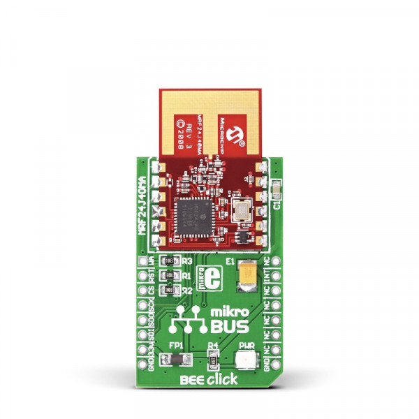
BEE click features MRF24J40MA 2.4 GHz IEEE 802.15.4 radio transceiver module from Microchip. The click is designed to run on 3.3V power supply only. It communicates with the target microcontroller over an SPI interface.
BEE click is an ideal solution for wireless networks, smart home and building automation, and other electronic applications that need wireless communication.
MRF24J40MA module
MRF24J40MA is IEEE 802.15.4™ standard compliant RF transceiver. It supports ZigBee®, MiWi™, MiWi P2P and proprietary wireless networking protocols with data rates of 250 kbps (IEEE 802.15.4).
PCB antenna
This module includes an integrated PCB antenna and matching circuitry and is connected to the microcontroller via an SPI interface.
Power supply
The board is designed to use 3.3V power supply only. If you need to add ZigBee™ feature to your 5V prototype or development board, we recommend you to use other boards such as the EasyBee 3 board.
Specification
| Type | ZigBee |
| Applications | BEE click is a great choice for building automation & monitoring, Industrial monitoring, Automated meter reading, Security, Inventory management and more. |
| On-board modules | 2.4 GHz IEEE 802.15.4 radio transceiver module MRF24J40MA |
| Key Features | Integrated 20 MHz and 32.768 kHz Crystal Oscillator Circuitry. Data Rate: 250 kbps (IEEE 802.15.4); 625 kbps (Turbo mode) |
| Key Benefits | Supports ZigBee®, MiWi™, MiWi P2P and Proprietary Wireless Networking Protocols |
| Interface | GPIO,SPI |
| Input Voltage | 3.3V |
| Compatibility | mikroBUS |
| Click board size | M (42.9 x 25.4 mm) |
Key features
- PCB antenna
- MRF24J40MA module
- Low current consumption (Tx 23mA, Rx 19mA, Sleep 2uA)
- ZigBee stack
- MiWi™ stack
- Interface: SPI
- 3.3V power supply
Pinout diagram
This table shows how the pinout on BEE click corresponds to the pinout on the mikroBUS™ socket (the latter shown in the two middle columns).
| Notes | Pin | mikroBUStm | Pin | Notes | |||
|---|---|---|---|---|---|---|---|
| External wake-up trigger | WA | 1 | AN | PWM | 16 | NC | Not connected |
| Global hardware Reset pin | RST# | 2 | RST | INT | 15 | INT | Interrupt pin |
| Serial interface enable | CS# | 3 | CS | TX | 14 | NC | Not connected |
| Serial interface clock | SCK | 4 | SCK | RX | 13 | NC | Not connected |
| Serial interface data output | SDO | 5 | MISO | SCL | 12 | NC | Not connected |
| Serial interface data input | SDI | 6 | MOSI | SDA | 11 | NC | Not connected |
| Power supply | +3.3V | 7 | 3.3V | 5V | 10 | NC | Not connected |
| Ground | GND | 8 | GND | GND | 9 | GND | Ground |
Programming
Code examples for BEE click, written for MikroElektronika hardware and compilers are available on Libstock.
This example transmits the data via the radio transceiver module, and displays it on the TFT display. For every pass it increments data.
01 void main() {
02   Initialize();                      // Initialize MCU and Bee click board
03   DrawFrame();
04
05   while(1) {                         // Infinite loop
06     write_TX_normal_FIFO();          // Transmiting
07     ByteToStr(DATA_TX[0],&txt);      // Convert byte to string
08     TFT_Set_Font(&TFT_defaultFont, CL_BLACK, FO_HORIZONTAL);
09     TFT_Write_Text(txt, 215, 80);    // Display string on TFT
10     delay_ms(1000);
11     TFT_Set_Font(&TFT_defaultFont, CL_WHITE, FO_HORIZONTAL);