
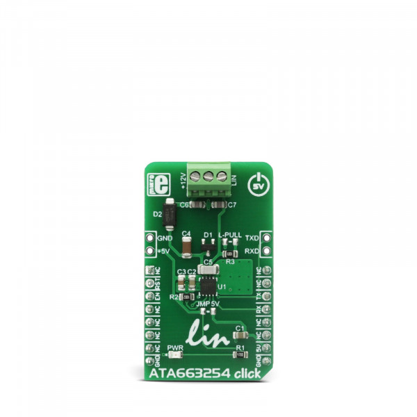
ATA663254 click


- Order number: MIKROE-2872
- Manufacturer product ID: MIKROE-2872
ATA663254 click is a fully integrated LIN transceiver device with an integrated 5V LDO voltage regulator. The combination of voltage regulator and bus transceiver makes it possible to develop simple but powerful slave nodes in LIN bus systems. The integrated LDO can be used to provide power to the host MCU so that no additional voltage regulators are required, only the power supply connected to the LIN connector is needed. ATA663254 click features the undervoltage protection, short-circuit protection, TXD time-out timer and its LIN physical layer complies with LIN 2.0, 2.1, 2.2, 2.2A and SAEJ2602-2 standard specifications.
These features make ATA663254 click a perfect solution for realizing small and portable LIN based networks that are commonly used in automotive applications for communicating with the vehicle sensor peripherals, but also for any application where robust and interference-free communication up to 20Kbps is needed.
How does it work?
LIN (Local Interconnect Network) is a serial network protocol used for communication between components in vehicles. LIN networks are cheaper than CAN networks and since the LIN network can have up to 15 slave nodes, it is often used as a subnetwork of CAN.
ATA663254 click uses the ATA663254 integrated LIN bus transceiver with the 5V voltage regulator from Microchip. The ATA663254 communicates with the MCU by using the UART RX and TX signals. Besides for communication, these pins also serve to signal the failsafe condition. The failsafe condition can be caused by the undervoltage on the LIN connector: less than 3.9V will cause the undervoltage condition, signaled by the LOW logic state on RX pin and HIGH logic state on the TX pin. A wake-up event from either silent or sleep mode is signaled by the LOW logic state on both of the RX and TX pins. This event is being received via the LIN bus and it is used to switch the ATA663254 click to an active state. RX and TX signals are also routed to the header on the edge of the click board™ so they can be used independently of the mikroBUS™ socket.
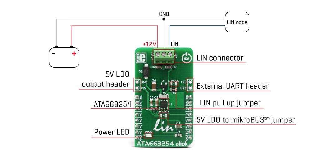
The NRES pin of the ATA663254 IC is routed to the RST pin on the mikroBUS™. RST pin is used to signal the undervoltage condition on the LDO regulator section. When the LDO voltage falls under the predefined threshold, the RST pin will be set to a LOW logic state, signaling this condition to the MCU. The LDO output is routed to a header located on the edge of the click so that the LDO can be used independently of the mikroBUS™ socket. Also, there is an SMD jumper that can be shorted if powering up the MCU via the mikroBUS™ 5V pin is required, on a custom board design. Note that the MikroElektronika development systems are not meant to be powered up by the mikroBUS™ power supply pins, so the ATA663254 click comes without the SMD jumper, by default.
The EN pin is used to enable the functionality of the device. When the EN pin is set to a HIGH logic level, the device is set to work in the normal mode, with the transmission paths from TXD to LIN and from LIN to RXD both active. When the EN pin is set to a LOW state, the device is put into silent mode, depending on the TX pin state. The EN pin has a pull-down resistor, so it is pulled to Ground if it is left afloat.
Besides the 5V LDO output header and the external UART header, the click is equipped with the three pole connector for an easy and secure connection to the LIN network and the 12V battery power supply.
Specifications
| Type | LIN |
| Applications | It can be used for small and portable LIN based networks, that are commonly used in automotive applications, but also for any application where robust and interference-free communication up to 20Kbps is needed. |
| On-board modules | ATA663254 integrated LIN bus transceiver with the 5V voltage regulator from Microchip |
| Key Features | Complete integrated LIN solution, with a 5V LDO that can be used for powering up other LIN nodes in the network, as well as the MCU. The onboard connector provides a secure and easy connection to the LIN network. |
| Interface | GPIO,UART |
| Input Voltage | 5V |
| Click board size | M (42.9 x 25.4 mm) |
Pinout diagram
This table shows how the pinout on ATA663254 click corresponds to the pinout on the mikroBUS™ socket (the latter shown in the two middle columns).
| Notes | Pin | Pin | Notes | ||||
|---|---|---|---|---|---|---|---|
| NC | 1 | AN | PWM | 16 | NC | ||
| Reset | RST | 2 | RST | INT | 15 | NC | |
| Enable | EN | 3 | CS | RX | 14 | TX | Transmit |
| NC | 4 | SCK | TX | 13 | RX | Receive | |
| NC | 5 | MISO | SCL | 12 | NC | ||
| NC | 6 | MOSI | SDA | 11 | NC | ||
| NC | 7 | 3.3V | 5V | 10 | 5V | Power Supply | |
| Ground | GND | 8 | GND | GND | 9 | GND | Ground |
ATA663254 click electrical specifications
| Description | Min | Typ | Max | Unit |
|---|---|---|---|---|
| LIN operating voltage range | 5 | 13.5 | 28 | V |
| Integrated LDO output current | 85 | mA | ||
| Integrated LDO output voltage | 4.9 | 5.1 | V |
Additional pins
| Name | I/O | Description |
|---|---|---|
| +5V | O | +5V Supply Output |
| GND | / | Power Ground |
| RXD | I/O | External UART RX Pad |
| TXD | I/O | External UART TX Pad |
Onboard settings and indicators
| Label | Name | Default | Description |
|---|---|---|---|
| LD1 | PWR | - | Power LED indicator |
| JMPR1 | JMP 5V | Unpopulated | Connects +5V output to mikroBUS™ socket |
| JMPR2 | L-PULL | Unpopulated | External LIN pull up resistor |
Software support
We provide a library for ATA663254 click on our LibStock page, as well as a demo application (example), developed using MikroElektronika compilers and mikroSDK. The provided click library is mikroSDK standard compliant. The demo application can run on all the main MikroElektronika development boards.
Library Description
Defines and initializes driver's UART bus. Declares and defines driver's functions for sending and receiving data bytes,
also for checking if the data byte is ready for reading.
void ata663254_enable(uint8_t state);- Function enables and disables click
void ata663254_writeByte(uint8_t input);- Function writes (sends) one byte in the RX buffer
uint8_t ata663254_readByte();- Function reads (receives) one byte from the RX buffer
uint8_t ata663254_ready();- Function checks if new data placed in the RX buffer
uint8_t ata663254_getRstState();- Function checks RST pin if undervoltage detection happens
Examples Description
- System Initialization - Initializes peripherals and pins
- Application Initialization - Initializes click driver
- The receiver part of the task logs each received byte to the UART bus, used for data logging. Transmitter part of the task sends a message every two seconds.
void applicationTask()
{
// RECEIVER
#ifdef __RX__
if(ata663254_ready())
{
tmp = ata663254_readByte();
mikrobus_logWrite(&tmp, _LOG_BYTE);
}
#endif
// TRANSMITER
#ifdef __TX__
uint8_t cnt;
for (cnt = 0; cnt < 9; cnt++)
{
ata663254_writeByte(MESSAGE_DATA[cnt]);
}
Delay_ms(2000);
#endif
}
The full application code and ready to use projects can be found on our LibStock page. Additional notes and information
Depending on the development board you are using, you may need USB UART click, USB UART 2 clickor RS232 click to connect to your PC, for development systems with no UART to USB interface available on the board. The terminal available in all MikroElektronika compilers, or any other terminal application of your choice, can be used to read the message.
mikroSDK
This click board is supported with mikroSDK - MikroElektronika Software Development Kit. To ensure proper operation of mikroSDK compliant click board demo applications, mikroSDK should be downloaded from the LibStock and installed for the compiler you are using.
For more information about mikroSDK, visit the official page.