
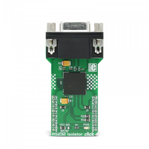
RS232 Isolator click


Prices incl. VAT plus shipping costs
Ready to ship today,
Delivery time appr. 1-3 workdays
- Order number: MIKROE-2864
- Manufacturer product ID: MIKROE-2864
RS232 Isolator click is a fully isolated dual transceiver click, used to provide secure and easy UART to RS232 conversion, with the galvanic isolation. The digital input and output signals are transmitted across the isolation barrier by utilizing the Analog Devices proprietary iCoupler® technology - IC scale transformer windings couple the digital signals magnetically, from one side of the barrier to the other, providing the galvanic isolation and transfer rates up to 460Kbps.
RS232 Isolator click can be used for galvanic isolation of RS232 signals, whenever there is a need for that kind of isolation - operating in harsh environments where electrostatic discharges (ESD) can occur, when the RS232 cable is plugged in and out frequently, and generally - wherever the sensitive part of the RS232 controller logic circuitry needs to be protected.
How does it work?
The RS232 is a serial communication standard, which was first introduced in ’60s. It became very popular during ’90s, as it became an integral part of many PC motherboards. After several reviews of this standard and thanks to its simplicity and past ubiquity, RS232 is still being used - particularly in industrial machines, networking equipment, and scientific instruments where a short-range, point-to-point, low-speed wired data connection is required.
The logic voltage levels used by the RS232 can go up to ±15V with respect to the common ground. This is very different than the CMOS/TTL voltage levels used on many MCUs and other types of commonly used modern devices, so the first task of the RS232 isolator board is to provide appropriate RS232/TTL levels.
The main active component of the RS232 Isolator click is the ADM3252E, an integrated dual channel RS232 driver/receiver, with the iCoupler® isolation technology, made by Analog Devices. This integrated circuit features four integrated galvanic isolation elements that provide the required isolation level. RS232 level inputs are inverted and encoded into waveforms that are used to energize the primary windings of the integrated transformers. At the secondary windings, the induced waveforms are decoded back into the digital values and routed to the pins, with the appropriate TTL/CMOS voltage levels. The same working principle is applied in the opposite direction, too. This way, the digital signals are effectively conducted through the isolation barrier.
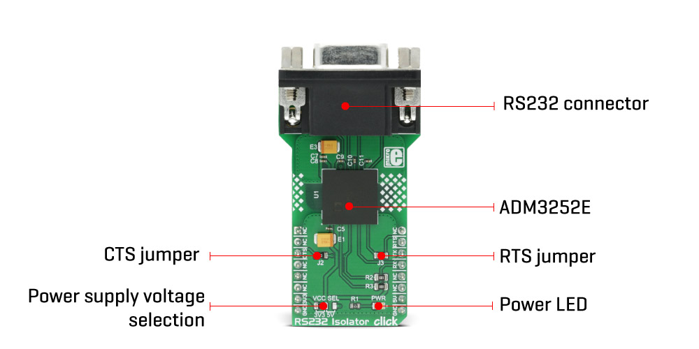
Besides the UART RX and TX lines, the click also supports the hardware flow control via the CTS and RTS lines. One of the two existing channels is used for the UART data communication itself, while the other channel is used for the hardware flow control lines. The usage of the control lines is not always mandatory, so the lines can be disconnected from the mikroBUS if needed, by unsoldering the SMD jumpers labeled as J1 and J2.
The ADM3252E IC also features the isoPower™ technology - an integrated DC-DC converter for generating all the required voltage levels, making it possible to power the click board™ by 3.3V or 5V. The operating voltage for the click board™ can be set with the onboard SMD jumper.
RS232 Isolator click features the onboard D-Sub 9 (DE9) connector for an easy and secure connection.
Specifications
| Type | RS232 |
| Applications | For applications which operate in harsh, industrial environments, when the RS23 cable is plugged in and out frequently. It can be used whenever the sensitive control circuitry needs to be isolated from the RS232 line levels. |
| On-board modules | ADM3252E, an isolated, dual channel, RS-232 line driver/receiver from Analog Devices |
| Key Features | High voltage galvanic isolation of RS232 lines, high speed communication, up to 460 Kbps, D-Sub connector for easy connection |
| Interface | GPIO,UART |
| Input Voltage | 3.3V or 5V |
| Click board size | L (57.15 x 25.4 mm) |
Pinout diagram
This table shows how the pinout on RS232 Isolator click corresponds to the pinout on the mikroBUS™ socket (the latter shown in the two middle columns).
| Notes | Pin | Pin | Notes | ||||
|---|---|---|---|---|---|---|---|
| NC | 1 | AN | PWM | 16 | NC | ||
| NC | 2 | RST | INT | 15 | RTS | Request to Send | |
| Clear to Send | CTS | 3 | CS | RX | 14 | TXD | Transmit Data |
| NC | 4 | SCK | TX | 13 | RXD | Receive Data | |
| NC | 5 | MISO | SCL | 12 | NC | ||
| NC | 6 | MOSI | SDA | 11 | NC | ||
| Power Supply | +3.3V | 7 | 3.3V | 5V | 10 | +5V | Power Supply |
| Ground | GND | 8 | GND | GND | 9 | GND | Ground |
RS232 Isolator click electrical specifications
| Description | Min | Typ | Max | Unit |
|---|---|---|---|---|
| Receiver inputs voltage range | -30 | +30 | V |
Onboard settings and indicators
| Label | Name | Default | Description |
|---|---|---|---|
| LD1 | PWR | - | Power LED indicator |
| J1 | VCC SEL | Left | Power supply voltage selection: left position 3V3, right position 5V |
| J2 | J2 | Soldered | CTS connection to mikroBUS™ |
| J3 | J3 | Soldered | RTS connection to mikroBUS™ |
| CN1 | RS232 | - | RS232 connector |
Software support
We provide an example for RS232 Isolator click inside all of our compilers. You can navigate to the demo using Project Explorer placed inside the folder named same as your development system.
Examples Description
Example application acts as a simple echo and each character is sent using the available terminal in all MikroElektronika compilers. Also, any other terminal of your choice can be used to write and read the messages.
char uard_rd;
void main()
{
UART1_Init(9600);               // Initialize UART module at 9600 bps
Delay_ms(100);                  // Wait for UART module to stabilize
UART1_Write_Text("Start");
UART1_Write(13);
UART1_Write(10);
while (1)
{
if (UART1_Data_Ready())
{
uart_rd = UART1_Read();     // read the received data,
UART1_Write(uart_rd);       // and send data via UART
}
}
}